
Circuit Documentation
Summary of the Circuit
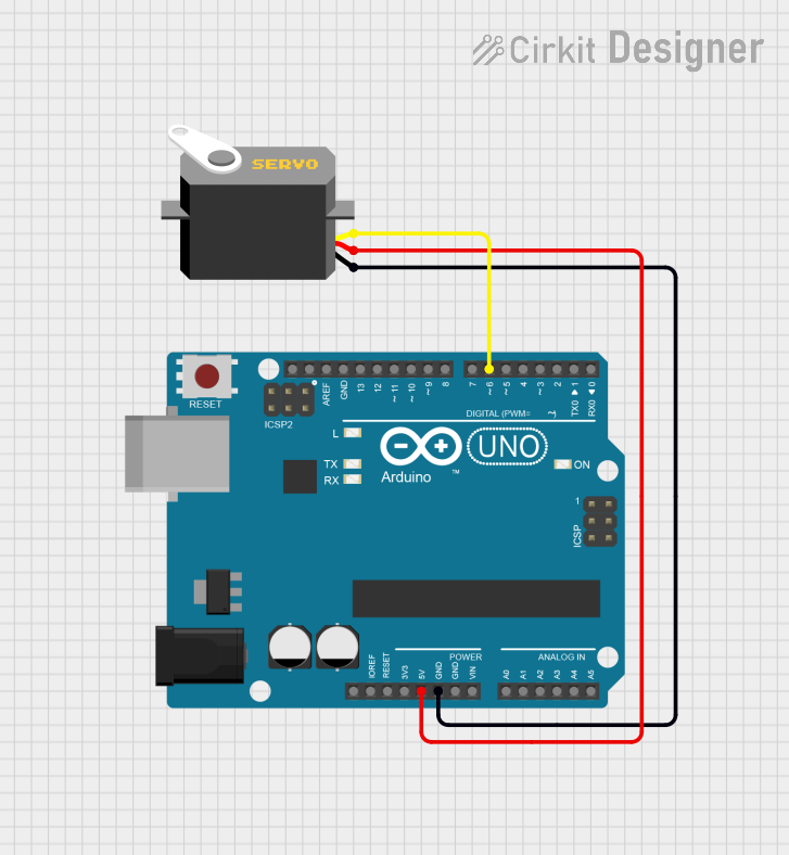
This circuit consists of an Arduino UNO microcontroller board and a servo motor. The Arduino UNO is used to control the position of the servo motor by sending pulse-width modulation (PWM) signals through one of its digital pins. The servo motor is powered directly from the Arduino's 5V output and is grounded to the Arduino's ground (GND) pin. The control signal for the servo is provided by the Arduino's digital pin 6 (D6).
Component List
Arduino UNO
- Description: A microcontroller board based on the ATmega328P.
- Pins Used:
IOREFReset3.3V5VGNDVinA0toA5SCLSDAAREFD0toD13
Servo Motor
- Description: A rotary actuator or linear actuator that allows for precise control of angular or linear position.
- Pins Used:
gndvccpulse
Wiring Details
Arduino UNO
- 5V to Servo Motor
vcc(Power supply for the servo motor) - GND to Servo Motor
gnd(Common ground reference) - D6 to Servo Motor
pulse(Control signal for the servo motor)
Servo Motor
- vcc connected to Arduino UNO
5V(Power supply from the Arduino) - gnd connected to Arduino UNO
GND(Common ground reference) - pulse connected to Arduino UNO
D6(Receives control signal from the Arduino)
Documented Code
#include <Servo.h>
Servo Inuka;

void setup() {
  // Attach the servo on pin 6 to the servo object
  Inuka.attach(6);
}

void loop() {
  // Set the servo position to 100 degrees
  Inuka.write(100);
}
- Filename:
servo.ino - Description: This code snippet is for the Arduino UNO microcontroller. It includes the Servo library, which provides easy control of the servo motor. In the
setup()function, the servo motor is attached to digital pin 6. Theloop()function sets the servo to a fixed position of 100 degrees continuously.