
Arduino-Controlled RGB LED Strip and Water Pump Activation System
View and Edit Project In Cirkit Designer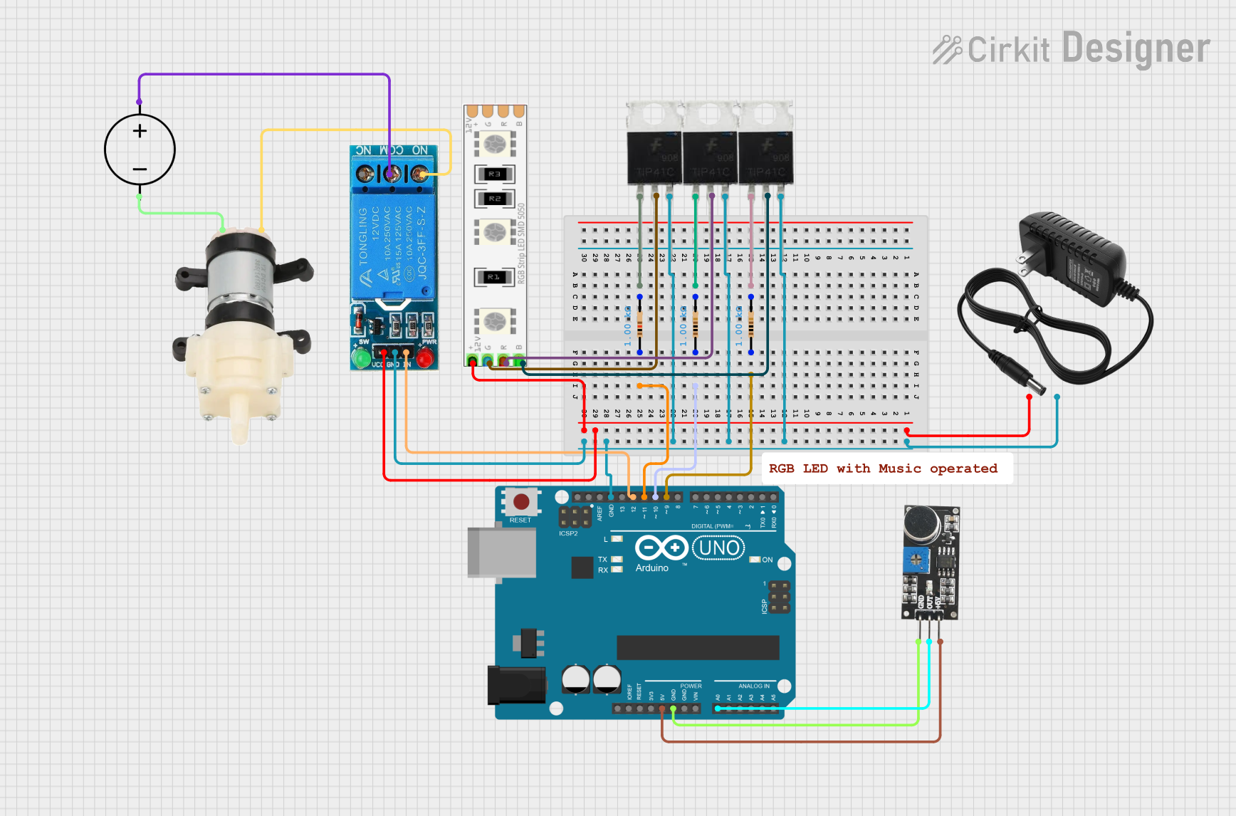
Circuit Documentation
Summary
This circuit is designed to control a 12V RGB LED strip and a mini diaphragm water pump based on input from a sound sensor. The RGB LED strip's color changes according to the filtered sound signal, and the relay activates the water pump when the sound signal exceeds a certain threshold. An Arduino UNO microcontroller is used to process the sound sensor signal and control the LED strip and relay. The circuit also includes power supply components and transistors to drive the LED strip and pump.
Component List
Transistors
- TIP41C - NPN power transistor used to switch the RGB LED strip channels and the relay for the water pump.
Resistors
- Resistor (1k Ohm) - Three resistors used to limit the base current of the TIP41C transistors.
Power Supplies
- 12V Power Supply - Provides power to the RGB LED strip and the relay.
- DC Power Source - Provides power to the mini diaphragm water pump.
Microcontroller
- Arduino UNO - Controls the RGB LED strip colors and the relay operation based on the sound sensor input.
Sensors
- Sound Sensor - Detects sound levels and sends the data to the Arduino UNO for processing.
Actuators
- 12V RGB LED Strip - Displays colors controlled by the Arduino UNO.
- Mini Diaphragm Water Pump - Pump activated by the relay when the sound threshold is exceeded.
Relay
- 12V Single Channel Relay - Switches the water pump on and off based on the control signal from the Arduino UNO.
Wiring Details
TIP41C Transistors
- Base - Connected to a 1k Ohm resistor.
- Collector - Connected to the RGB LED strip's respective color channel or the relay's common (COM) terminal.
- Emitter - Connected to the ground of the 12V power supply.
Resistors (1k Ohm)
- One side connected to the Arduino UNO's digital pins (D9, D10, D11).
- The other side connected to the base of the respective TIP41C transistor.
12V Power Supply
- + - Connected to the VCC of the relay and the 12V+ of the RGB LED strip.
- - - Connected to the emitter of the TIP41C transistors, GND of the relay, and GND of the Arduino UNO.
Arduino UNO
- Digital Pins (D9, D10, D11) - Connected to the resistors that control the TIP41C transistors.
- Digital Pin (D12) - Connected to the relay's input (IN) to control the water pump.
- Analog Pin (A0) - Connected to the sound sensor's output (OUT).
- 5V and GND - Provide power to the sound sensor.
Sound Sensor
- 5V+ - Connected to the 5V output of the Arduino UNO.
- OUT - Connected to the A0 analog input of the Arduino UNO.
- GND - Connected to the ground of the Arduino UNO.
12V RGB LED Strip
- 12V+ - Connected to the + of the 12V power supply.
- R, G, B Channels - Each connected to the collector of a respective TIP41C transistor.
Mini Diaphragm Water Pump
- Positive (+) - Connected to the normally open (NO) terminal of the relay.
- Negative (-) - Connected to the ground of the DC power source.
12V Single Channel Relay
- VCC - Connected to the + of the 12V power supply.
- GND - Connected to the ground of the 12V power supply.
- IN - Connected to the D12 digital pin of the Arduino UNO.
- COM - Connected to the positive of the DC power source.
- NO - Connected to the positive terminal of the mini diaphragm water pump.
DC Power Source
- Positive - Connected to the common (COM) terminal of the relay.
- Ground - Connected to the negative terminal of the mini diaphragm water pump.
Documented Code
/*
 * This Arduino sketch controls an RGB LED strip and a relay with a motor
 * based on input from a sound sensor. The RGB LED strip changes colors
 * according to the filtered sound signal, and the relay activates the motor
 * when the sound signal exceeds a certain threshold.
 */

#define Rpin 11
#define Gpin 10
#define Bpin 9
#define relayPin 12
#define sensorPin A0
#define delayLEDS 3

float sensorValue = 0, filteredSignal = 0,
    filteredSignalValues[] = {3.4, 3.1, 2.7, 2.4, 2.1, 1.7, 1.3, 0.9, 0.4};

void setup() {
  Serial.begin(9600);
  pinMode(Rpin, OUTPUT);
  pinMode(Gpin, OUTPUT);
  pinMode(Bpin, OUTPUT);
  pinMode(relayPin, OUTPUT);
}

void loop() {
  MainFunction();
}

void MainFunction() {
  sensorValue = (float)analogRead(sensorPin) * (5.0 / 1024.0);
  FilterSignal(sensorValue);
  Serial.print(sensorValue);
  Serial.print(" ");
  Serial.println(filteredSignal);
  CompareSignalFiltered(filteredSignal);
}

void FilterSignal(float sensorSignal) {
  filteredSignal = (0.945 * filteredSignal) + (0.0549 * sensorSignal);
}

void CompareSignalFiltered(float filteredSignal) {
  if (filteredSignal > filteredSignalValues[0]) {
    RGBColor(0, 0, 255);
    Serial.println("Blue");
    digitalWrite(relayPin, HIGH);
  } else if (filteredSignal <= filteredSignalValues[0] &&
             filteredSignal > filteredSignalValues[1]) {
    RGBColor(0, 255, 255);
    Serial.println("Azure");
    digitalWrite(relayPin, LOW);
  } else if (filteredSignal <= filteredSignalValues[1] &&
             filteredSignal > filteredSignalValues[2]) {
    RGBColor(0, 127, 255);
    Serial.println("Cyan");
    digitalWrite(relayPin, LOW);
  } else if (filteredSignal <= filteredSignalValues[2] &&
             filteredSignal > filteredSignalValues[3]) {
    RGBColor(0, 255, 127);
    Serial.println("Aqua marine");
    digitalWrite(relayPin, LOW);
  } else if (filteredSignal <= filteredSignalValues[3] &&
             filteredSignal > filteredSignalValues[4]) {
    RGBColor(0, 255, 0);
    Serial.println("Green");
    digitalWrite(relayPin, LOW);
  } else if (filteredSignal <= filteredSignalValues[4] &&
             filteredSignal > filteredSignalValues[5]) {
    RGBColor(255, 255, 0);
    Serial.println("Yellow");
    digitalWrite(relayPin, LOW);
  } else if (filteredSignal <= filteredSignalValues[5] &&
             filteredSignal > filteredSignalValues[6]) {
    RGBColor(255, 0, 255);
    Serial.println("Magenta");
    digitalWrite(relayPin, LOW);
  } else if (filteredSignal <= filteredSignalValues[6] &&
             filteredSignal > filteredSignalValues[7]) {
    RGBColor(255, 0, 127);
    Serial.println("Rose");
    digitalWrite(relayPin, LOW);
  } else if (filteredSignal <= filteredSignalValues[7] &&
             filteredSignal > filteredSignalValues[8]) {
    RGBColor(255, 127, 0);
    Serial.println("Orange");
    digitalWrite(relayPin, LOW);
  } else if (filteredSignal <= filteredSignalValues[8]) {
    RGBColor(255, 0, 0);
    Serial.println("Red");
    digitalWrite(relayPin, LOW);
  } else {
    RGBColor(0, 0, 255);
    Serial.println("Default: Blue");
    digitalWrite(relayPin, LOW);
  }
}

void RGBColor(int Rcolor, int Gcolor, int Bcolor) {
  analogWrite(Rpin, Rcolor);
  analogWrite(Gpin, Gcolor);
  analogWrite(Bpin, Bcolor);
  delay(delayLEDS);
}
This code is designed to be uploaded to an Arduino UNO microcontroller. It reads the analog value from a sound sensor, filters the signal, and then uses the filtered value to determine the color of the RGB LED strip and whether to activate the relay for the water pump. The colors and relay state are adjusted based on predefined threshold values.