
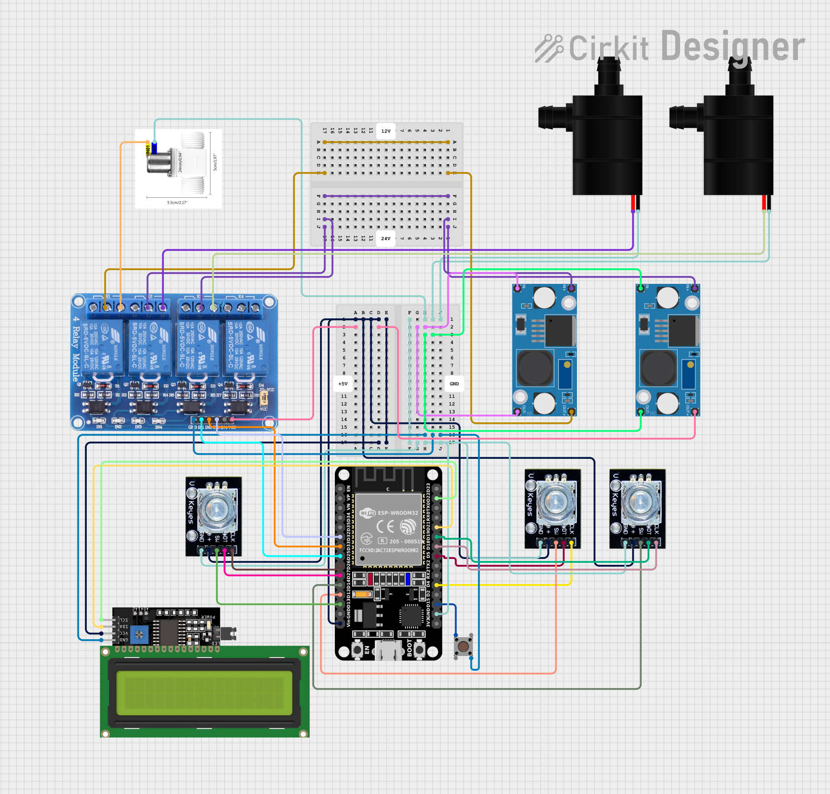
Circuit Documentation
Summary
This circuit is designed to control various devices such as water pumps, a valve solenoid, and to interact with a user through rotary encoders and a pushbutton. The central processing unit is an ESP32 microcontroller, which manages input from the rotary encoders and the pushbutton, and controls the relay module to switch the water pumps and valve solenoid. The circuit also includes an LCD display for user interface, which is connected to the ESP32 via I2C communication. Power management is handled by two LM2596 Step Down Modules, which provide regulated voltage to the components.
Component List
ESP32 (30 pin)
- Microcontroller with WiFi and Bluetooth capabilities.
- It has a variety of digital I/O pins and supports serial communication.
Relay 4 Channel 5v
- A module with 4 relays that can control high power devices.
- Each relay has a Normally Open (NO) and a Normally Closed (NC) contact.
Rotary Encoder (x3)
- Input devices that provide rotational position feedback.
- Each encoder has a clock, data, and switch pin for interfacing.
Pushbutton
- A simple switch that connects two contacts when pressed.
LCD Display 16x4 I2C
- An alphanumeric liquid crystal display with 16 characters per line and 4 lines.
- Uses I2C communication for interfacing with the microcontroller.
LM2596 Step Down Module (x2)
- Voltage regulators that step down input voltage to a lower output voltage.
- Each module has input and output terminals for voltage and ground.
Water Pump (x2)
- Pumps used for moving water.
- Each pump has a voltage and ground connection.
Valve Solenoid Water
- An electrically-controlled valve used for controlling the flow of water.
Wiring Details
ESP32 (30 pin)
Vinconnected to power supply along with Rotary Encoders and LCD Display.GNDconnected to common ground.D32,D33,D25connected to Relay 4 Channel inputsIN3,IN2,IN1respectively.D26,D27,D14,D12,D13connected to Rotary Encoders'clk,dt,swpins respectively.D22,D21connected to LCD Display'sSCL,SDApins for I2C communication.D19,D18,D5,D4,D15connected to Rotary Encoders'dt,clk,swpins and Pushbutton'sPin 4 (out)respectively.
Relay 4 Channel 5v
VCCconnected to LM2596 Step Down Module'sOUT+.GNDconnected to common ground.IN1,IN2,IN3controlled by ESP32 pinsD25,D33,D32.COM1connected to LM2596 Step Down Module'sOUT+.COM2,COM3connected to LM2596 Step Down Module'sIN+.NO1,NO2,NO3connected to Valve Solenoid Water'sIN01and Water Pumps'VCC.
Rotary Encoder (x3)
clk,dt,swpins connected to ESP32'sD26,D27,D14,D12,D13,D19,D18,D5,D4.+pin connected to power supply.gndpin connected to common ground.
Pushbutton
Pin 1 (in)connected to common ground.Pin 4 (out)connected to ESP32'sD15.
LCD Display 16x4 I2C
SCL,SDApins connected to ESP32'sD22,D21for I2C communication.VCCconnected to power supply.GNDconnected to common ground.
LM2596 Step Down Module (x2)
OUT+,OUT-connected to Relay 4 ChannelVCCandGND.IN+,IN-connected to power supply and common ground.
Water Pump (x2)
VCCconnected to Relay 4 ChannelNO2,NO3.GNDconnected to common ground.
Valve Solenoid Water
IN01connected to Relay 4 ChannelNO1.IN02connected to common ground.
Documented Code
There is no code provided for the microcontroller. The code would typically include initialization of the I/O pins, setup of the I2C communication for the LCD display, and the main loop handling the logic for reading the rotary encoders, debouncing the pushbutton, and controlling the relay module based on the inputs.