
Circuit Documentation
Summary
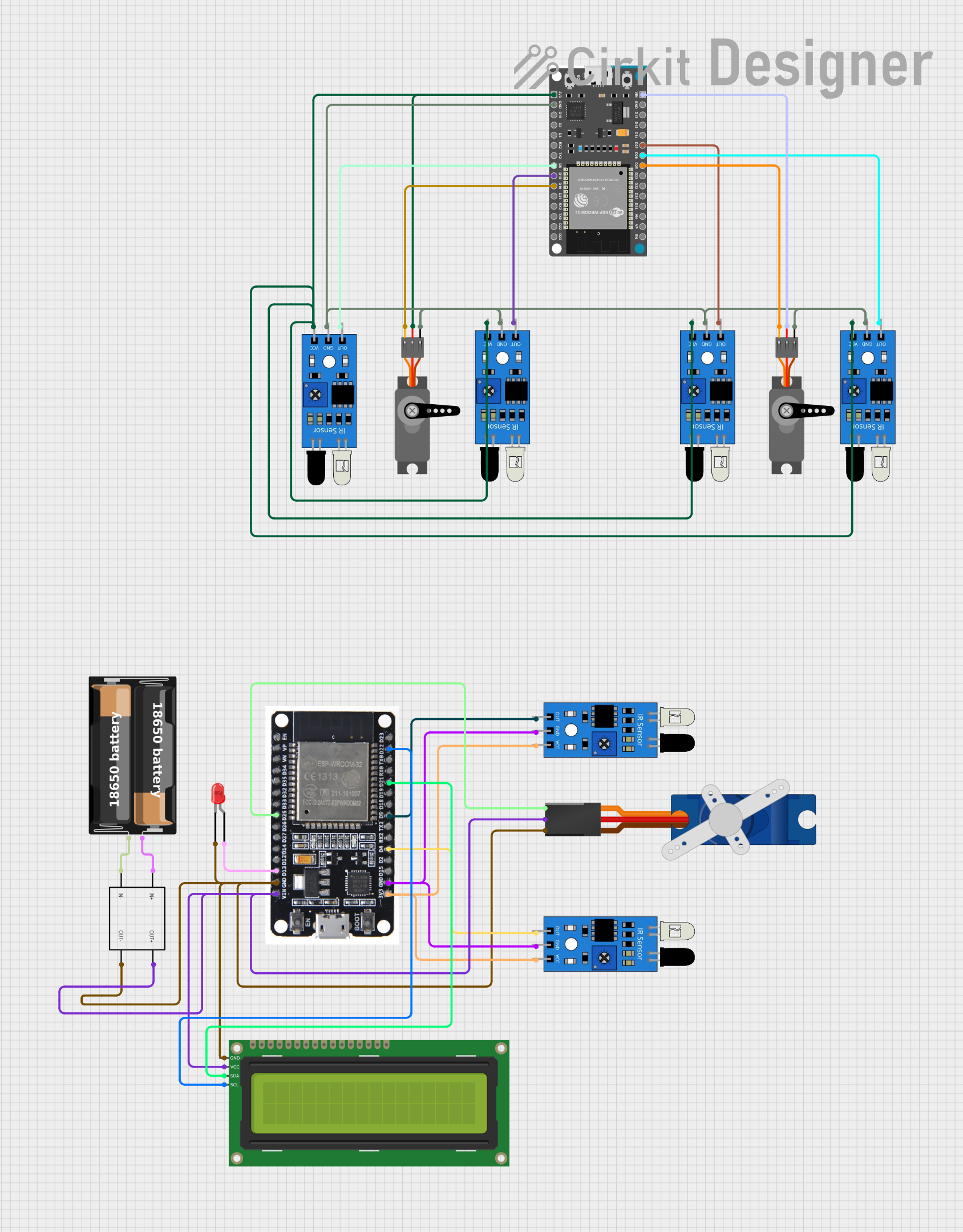
The circuit in question appears to be a control system utilizing an ESP32 Devkit V1 microcontroller as the central processing unit. It interfaces with multiple IR sensors and servo motors, indicating a potential application in object detection or distance sensing with actuation control. Additionally, there is a 16x2 I2C LCD for display purposes, a step-down converter to regulate voltage, and a battery case as the power source. The circuit also includes a red LED, which could serve as an indicator light.
Component List
Microcontrollers
- ESP32 Devkit V1: A powerful microcontroller with Wi-Fi and Bluetooth capabilities, featuring a variety of digital I/O pins.
- ESP32: Similar to the Devkit, this microcontroller also offers Wi-Fi and Bluetooth functionality and a range of I/O options.
Sensors
- IR Sensors: Used for detecting objects or measuring distances by emitting and receiving infrared light.
Actuators
- Servo Motors: These are used to control the position of objects with precision. They receive PWM signals to set the angle of rotation.
Display
- 16x2 I2C LCD: A liquid crystal display that can show 16 characters per line, with 2 lines. It uses the I2C protocol for communication.
Power Management
- Step-Down Converter: This component steps down the input voltage to a lower output voltage, providing a regulated power supply to the circuit.
- My Battery Case: Serves as the power source for the circuit.
Indicators
- LED (Red): A simple light-emitting diode that can be used as an indicator.
Miscellaneous
- Tower Pro SG90 Servo: Another type of servo motor for precise control of mechanical movement.
Wiring Details
ESP32 Devkit V1
- 3V3: Connected to the VCC pins of multiple IR sensors and a Servo motor.
- GND: Common ground shared with IR sensors and a Servo motor.
- D5, D18, D19, D25, D26, D27: Digital pins connected to the output pins of IR sensors and PWM pins of Servo motors.
- VIN: Connected to the VCC pin of a Servo motor.
ESP32
- 3V3: Powers IR sensors.
- GND: Common ground for the LED, LCD, Step-Down Converter, Tower Pro SG90 servo, and IR sensors.
- D4, D5: Connected to the output pins of IR sensors.
- D13: Connected to the cathode of the red LED.
- D21, D22: I2C communication pins connected to the SDA and SCL pins of the 16x2 I2C LCD.
- VIN: Powers the Tower Pro SG90 servo and the 16x2 I2C LCD.
IR Sensors
- VCC: Powered by the 3V3 pins of the ESP32 and ESP32 Devkit V1.
- GND: Connected to the common ground.
- OUT: Output pins connected to various digital pins on the ESP32 and ESP32 Devkit V1 for signal processing.
Servo Motors
- VCC: Powered by the 3V3 or VIN pins of the ESP32 Devkit V1.
- GND: Connected to the common ground.
- PWM: Receive PWM signals from the ESP32 Devkit V1 for position control.
16x2 I2C LCD
- VCC: Powered by the OUT+ of the Step-Down Converter.
- GND: Connected to the common ground.
- SDA, SCL: I2C communication pins connected to the ESP32.
Step-Down Converter
- IN+, IN-: Connected to the positive and negative terminals of the battery case, respectively.
- OUT+, OUT-: Provide regulated voltage to the 16x2 I2C LCD and other components.
LED (Red)
- Anode: Connected to the D13 pin of the ESP32.
- Cathode: Connected to the common ground.
Tower Pro SG90 Servo
- +5V: Powered by the OUT+ of the Step-Down Converter.
- GND: Connected to the common ground.
- Signal: Receives control signals from the D25 pin of the ESP32.
My Battery Case
- +: Connected to the IN+ of the Step-Down Converter.
- -: Connected to the IN- of the Step-Down Converter.
Documented Code
No code was provided for the microcontrollers in the circuit. For a complete documentation, the embedded code that runs on the ESP32 and ESP32 Devkit V1 should be included, detailing the logic for sensor data acquisition, processing, actuator control, and any communication protocols used for interfacing with the LCD or external devices.