
Circuit Documentation
Summary
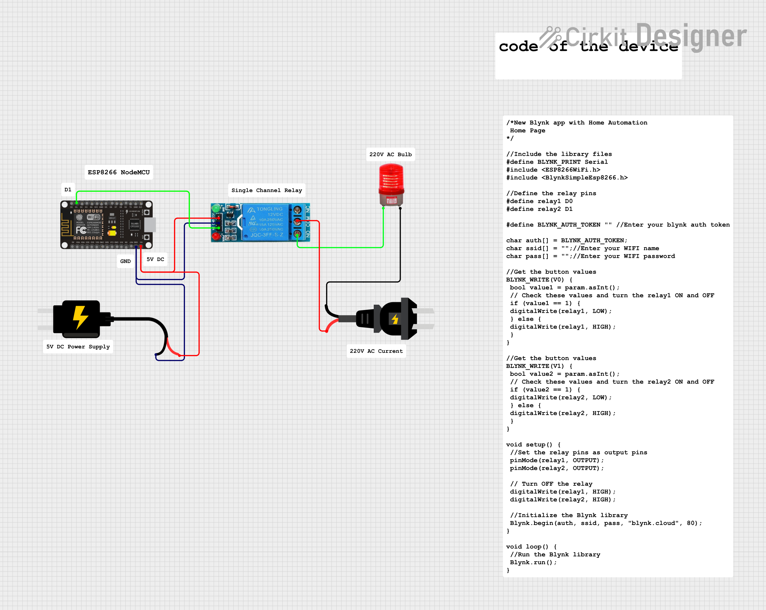
This circuit involves an ESP8266 NodeMCU microcontroller, a 12V single-channel relay, a 5V DC power source, a 220V AC power source, and a 220V AC red light. The ESP8266 NodeMCU controls the relay, which in turn controls the AC red light. The 5V DC power source powers both the ESP8266 NodeMCU and the relay.
Component List
12V Single Channel Relay
- Pins: NC, COM, NO, IN, GND, VCC
- Description: A relay module used to control high voltage devices with a low voltage signal.
ESP8266 NodeMCU
- Pins: D0, D1, D2, D3, D4, 3V3, GND, D5, D6, D7, D8, RX, TX, A0, RSV, SD3, SD2, SD1, CMD, SD0, CLK, EN, RST, VIN
- Description: A low-cost Wi-Fi microcontroller with GPIO, PWM, ADC, I2C, and 1-Wire resources.
DC Source 5V
- Pins: VCC, GND
- Description: A 5V DC power source.
Red Light 220VAC
- Pins: -, +
- Description: A red indicator light that operates on 220V AC.
AC Source
- Pins: -, +
- Description: A 220V AC power source.
Wiring Details
12V Single Channel Relay
- COM is connected to - of the AC Source.
- NO is connected to + of the Red Light 220VAC.
- IN is connected to D1 of the ESP8266 NodeMCU.
- GND is connected to GND of the DC Source 5V and GND of the ESP8266 NodeMCU.
- VCC is connected to VCC of the DC Source 5V and VIN of the ESP8266 NodeMCU.
ESP8266 NodeMCU
- D1 is connected to IN of the 12V Single Channel Relay.
- GND is connected to GND of the DC Source 5V and GND of the 12V Single Channel Relay.
- VIN is connected to VCC of the DC Source 5V and VCC of the 12V Single Channel Relay.
DC Source 5V
- VCC is connected to VCC of the 12V Single Channel Relay and VIN of the ESP8266 NodeMCU.
- GND is connected to GND of the 12V Single Channel Relay and GND of the ESP8266 NodeMCU.
Red Light 220VAC
- + is connected to NO of the 12V Single Channel Relay.
- - is connected to + of the AC Source.
AC Source
- - is connected to COM of the 12V Single Channel Relay.
- + is connected to - of the Red Light 220VAC.
Code
There is no code provided for this circuit.