
Arduino UNO Controlled Smart Home Lighting with Bluetooth and LCD Interface
View and Edit Project In Cirkit Designer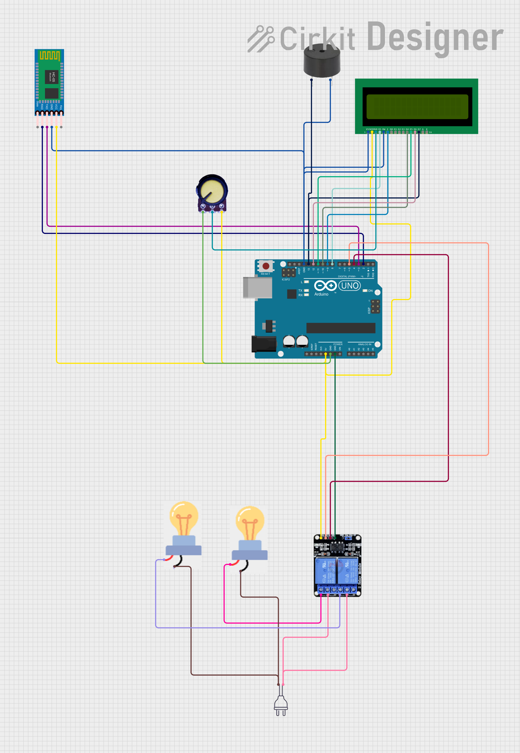
Circuit Documentation
Summary
The circuit in question is designed to interface an Arduino UNO with various peripherals including an HC-05 Bluetooth Module, a buzzer, a 16x2 LCD, a two-channel 5V relay, and two bulbs. The Arduino UNO serves as the central microcontroller unit, managing input and output signals to control the connected devices. The HC-05 Bluetooth Module allows for wireless communication, while the relay module controls power to the bulbs. The LCD displays information, and the buzzer provides audible alerts. A potentiometer is included to adjust the contrast of the LCD. The circuit is powered by a 5V supply from the Arduino and a separate 220V power source for the relay and bulbs.
Component List
Arduino UNO
- Microcontroller board based on the ATmega328P
- Digital I/O Pins: 14 (of which 6 provide PWM output)
- Analog Input Pins: 6
- Operating Voltage: 5V
HC-05 Bluetooth Module
- Wireless communication module for Bluetooth connectivity
- Operating Voltage: 3.3V to 6V
Buzzer
- An audible signaling device
- Operating Voltage: Typically 5V
16X2 LCD
- Alphanumeric Liquid Crystal Display
- 16 characters wide, 2 rows
- Operating Voltage: 5V
Two Channel Relay 5v
- Relay module with two channels
- Operating Voltage: 5V
Bulb
- Electric light source
- Operating Voltage: 220V
Potentiometer
- Three-terminal resistor with an adjustable voltage divider
- Operating Voltage: Typically 5V
Power 220v
- Main power supply
- Voltage: 220V AC
Wiring Details
Arduino UNO
- 5V to VCC of LCD, Potentiometer, Relay, and HC-05 Bluetooth Module
- GND to GND of Potentiometer, Relay, LCD, Buzzer, and HC-05 Bluetooth Module
- D13 to PIN of Buzzer
- D12 to D6 of LCD
- D11 to D5 of LCD
- D10 to D4 of LCD
- D9 to E of LCD
- D8 to RS of LCD
- D5 to IN2 of Relay
- D4 to IN1 of Relay
- D3 to TXD of HC-05 Bluetooth Module
- D2 to RXD of HC-05 Bluetooth Module
HC-05 Bluetooth Module
- VCC to 5V of Arduino UNO
- GND to GND of Arduino UNO
- TXD to D3 of Arduino UNO
- RXD to D2 of Arduino UNO
Buzzer
- PIN to D13 of Arduino UNO
- GND to GND of Arduino UNO
16X2 LCD
- VDD to 5V of Arduino UNO
- VSS, RW to GND of Arduino UNO
- V0 to Output of Potentiometer
- RS to D8 of Arduino UNO
- E to D9 of Arduino UNO
- D4 to D10 of Arduino UNO
- D5 to D11 of Arduino UNO
- D6 to D12 of Arduino UNO
- D7 to D13 of Arduino UNO
Two Channel Relay 5v
- VCC to 5V of Arduino UNO
- GND to GND of Arduino UNO
- IN1 to D4 of Arduino UNO
- IN2 to D5 of Arduino UNO
- NC1 to power of Bulb (instance a5f20df5-9651-4d78-b4fa-ebfcca759a8c)
- NC2 to power of Bulb (instance 3cff27f7-e5f6-4d75-8721-f6e7ae45d33a)
- C1, C2 to hot wire of Power 220v
Bulb (instance a5f20df5-9651-4d78-b4fa-ebfcca759a8c)
- power to NC1 of Relay
- GND to neutral wire of Power 220v
Bulb (instance 3cff27f7-e5f6-4d75-8721-f6e7ae45d33a)
- power to NC2 of Relay
- GND to neutral wire of Power 220v
Potentiometer
- VCC to 5V of Arduino UNO
- Output to V0 of LCD
- GND to GND of Arduino UNO
Power 220v
- hot wire to C1, C2 of Relay
- neutral wire to GND of Bulbs
Documented Code
Arduino UNO Code (sketch.ino)
void setup() {
  // put your setup code here, to run once:

}

void loop() {
  // put your main code here, to run repeatedly:

}
Note: The provided code for the Arduino UNO is a template with empty setup and loop functions. Actual functionality needs to be implemented based on the desired behavior of the circuit.