
Arduino UNO and ILI9341 TFT Display Interactive Graphics Demo
View and Edit Project In Cirkit Designer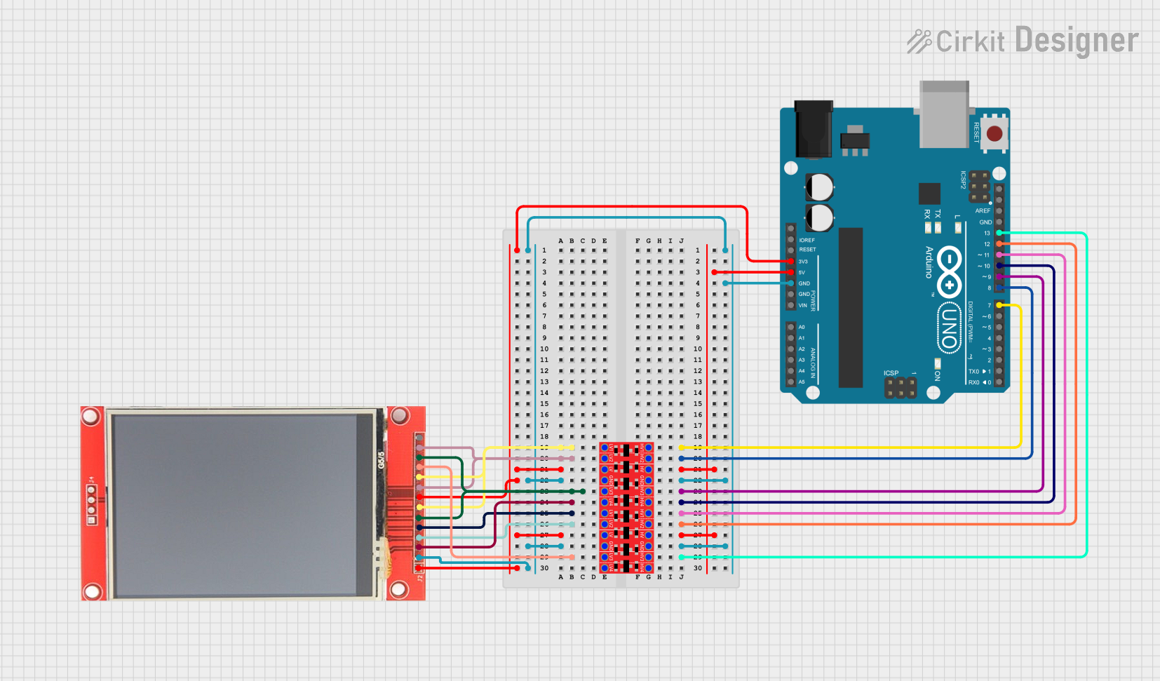
Circuit Documentation
Summary
This document provides a detailed overview of a circuit that integrates an Arduino UNO microcontroller, an ILI9341 TFT display, and two Bi-Directional Logic Level Converters. The circuit is designed to interface the Arduino with the TFT display using SPI communication, with the logic level converters ensuring proper voltage levels between the components.
Component List
Arduino UNO
- Description: A microcontroller board based on the ATmega328P.
- Pins: UNUSED, IOREF, Reset, 3.3V, 5V, GND, Vin, A0, A1, A2, A3, A4, A5, SCL, SDA, AREF, D13, D12, D11, D10, D9, D8, D7, D6, D5, D4, D3, D2, D1, D0
ILI9341 TFT Display
- Description: A 2.8" TFT LCD display with a resolution of 240x320 pixels, using the ILI9341 driver.
- Pins: VCC, GND, CS, RESET, DC/RS, SDI, SCK, LED, SDO, T_CLK, T_CS, T_DIN, T_DO, T_IRQ
Bi-Directional Logic Level Converter (2 units)
- Description: A device used to safely step down 5V signals to 3.3V and step up 3.3V signals to 5V.
- Pins: HV1, HV2, HV, GND, HV3, HV4, LV1, LV2, LV, LV3, LV4
Wiring Details
Arduino UNO
- D7: Connected to HV1 of Logic Level Converter 1
- D8: Connected to HV2 of Logic Level Converter 1
- D9: Connected to HV3 of Logic Level Converter 1
- D10: Connected to HV4 of Logic Level Converter 1
- D11: Connected to HV1 of Logic Level Converter 2
- D12: Connected to HV2 of Logic Level Converter 2
- D13: Connected to HV3 of Logic Level Converter 2
- 3.3V: Connected to LV of both Logic Level Converters and VCC, LED of TFT Display
- 5V: Connected to HV of both Logic Level Converters
- GND: Connected to GND of both Logic Level Converters and GND of TFT Display
ILI9341 TFT Display
- VCC: Connected to 3.3V of Arduino UNO
- GND: Connected to GND of Arduino UNO
- CS: Connected to LV4 of Logic Level Converter 1
- RESET: Connected to LV2 of Logic Level Converter 2
- DC/RS: Connected to LV1 of Logic Level Converter 2
- SDI: Connected to LV3 of Logic Level Converter 1
- SCK: Connected to LV1 of Logic Level Converter 1
- LED: Connected to 3.3V of Arduino UNO
- SDO: Connected to LV2 of Logic Level Converter 1
- T_CLK: Connected to LV1 of Logic Level Converter 1
- T_CS: Connected to LV3 of Logic Level Converter 2
- T_DIN: Connected to LV3 of Logic Level Converter 1
- T_DO: Connected to LV2 of Logic Level Converter 1
Bi-Directional Logic Level Converter 1
- HV1: Connected to D7 of Arduino UNO
- HV2: Connected to D8 of Arduino UNO
- HV3: Connected to D9 of Arduino UNO
- HV4: Connected to D10 of Arduino UNO
- LV1: Connected to SCK, T_CLK of TFT Display
- LV2: Connected to SDO, T_DO of TFT Display
- LV3: Connected to SDI, T_DIN of TFT Display
- LV4: Connected to CS of TFT Display
- LV: Connected to 3.3V of Arduino UNO
- HV: Connected to 5V of Arduino UNO
- GND: Connected to GND of Arduino UNO
Bi-Directional Logic Level Converter 2
- HV1: Connected to D11 of Arduino UNO
- HV2: Connected to D12 of Arduino UNO
- HV3: Connected to D13 of Arduino UNO
- LV1: Connected to DC/RS of TFT Display
- LV2: Connected to RESET of TFT Display
- LV3: Connected to T_CS of TFT Display
- LV: Connected to 3.3V of Arduino UNO
- HV: Connected to 5V of Arduino UNO
- GND: Connected to GND of Arduino UNO
Code Documentation
Arduino UNO Code
/***************************************************
  This is our GFX example for the Adafruit ILI9341 Breakout and Shield
  ----> http://www.adafruit.com/products/1651

  Check out the links above for our tutorials and wiring diagrams
  These displays use SPI to communicate, 4 or 5 pins are required to
  interface (RST is optional)
  Adafruit invests time and resources providing this open source code,
  please support Adafruit and open-source hardware by purchasing
  products from Adafruit!

  Written by Limor Fried/Ladyada for Adafruit Industries.
  MIT license, all text above must be included in any redistribution
 ****************************************************/

#include "SPI.h"
#include "Adafruit_GFX.h"
#include "Adafruit_ILI9341.h"

// For the Adafruit shield, these are the default.
#define TFT_DC 9
#define TFT_CS 10
#define TFT_RST 8

// Use hardware SPI (on Uno, #13, #12, #11) and the above for CS/DC
Adafruit_ILI9341 tft = Adafruit_ILI9341(TFT_CS, TFT_DC, TFT_RST);
// If using the breakout, change pins as desired
//Adafruit_ILI9341 tft = Adafruit_ILI9341(TFT_CS, TFT_DC, TFT_MOSI, TFT_CLK, TFT_RST, TFT_MISO);

void setup() {
  Serial.begin(9600);
  Serial.println("ILI9341 Test!");

 // deselect all SPI devices
 pinMode(TFT_CS, OUTPUT);
 pinMode (7, OUTPUT);
 digitalWrite (TFT_CS, HIGH);
 digitalWrite (7, HIGH);

  tft.begin();

  // read diagnostics (optional but can help debug problems)
  uint8_t x = tft.readcommand8(ILI9341_RDMODE);
  Serial.print("Display Power Mode: 0x"); Serial.println(x, HEX);
  x = tft.readcommand8(ILI9341_RDMADCTL);
  Serial.print("MADCTL Mode: 0x"); Serial.println(x, HEX);
  x = tft.readcommand8(ILI9341_RDPIXFMT);
  Serial.print("Pixel Format: 0x"); Serial.println(x, HEX);
  x = tft.readcommand8(ILI9341_RDIMGFMT);
  Serial.print("Image Format: 0x"); Serial.println(x, HEX);
  x = tft.readcommand8(ILI9341_RDSELFDIAG);
  Serial.print("Self Diagnostic: 0x"); Serial.println(x, HEX);

  Serial.println(F("Benchmark                Time (microseconds)"));
  delay(10);
  Serial.print(F("Screen fill              "));
  Serial.println(testFillScreen());
  delay(500);

  Serial.print(F("Text                     "));
  Serial.println(testText());
  delay(3000);

  Serial.print(F("Lines                    "));
  Serial.println(testLines(ILI9341_CYAN));
  delay(500);

  Serial.print(F("Horiz/Vert Lines         "));
  Serial.println(testFastLines(ILI9341_RED, ILI9341_BLUE));
  delay(500);

  Serial.print(F("Rectangles (outline)     "));
  Serial.println(testRects(ILI9341_GREEN));
  delay(500);

  Serial.print(F("Rectangles (filled)      "));
  Serial.println(testFilledRects(ILI9341_YELLOW, ILI9341_MAGENTA));
  delay(500);

  Serial.print(F("Circles (filled)         "));
  Serial.println(testFilledCircles(10, ILI9341_MAGENTA));

  Serial.print(F("Circles (outline)        "));
  Serial.println(testCircles(10, ILI9341_WHITE));
  delay(500);

  Serial.print(F("Triangles (outline)      "));
  Serial.println(testTriangles());
  delay(500);

  Serial.print(F("Triangles (filled)       "));
  Serial.println(testFilledTriangles());
  delay(500);

  Serial.print(F("Rounded rects (outline)  "));
  Serial.println(testRoundRects());
  delay(500);

  Serial.print(F("Rounded rects (filled)   "));
  Serial.println(testFilledRoundRects());
  delay(500);

  Serial.println(F("Done!"));

}

void loop(void) {
  for(uint8_t