ESP8266 NodeMCU Based Water Level Monitoring System

Circuit Documentation
Summary of the Circuit
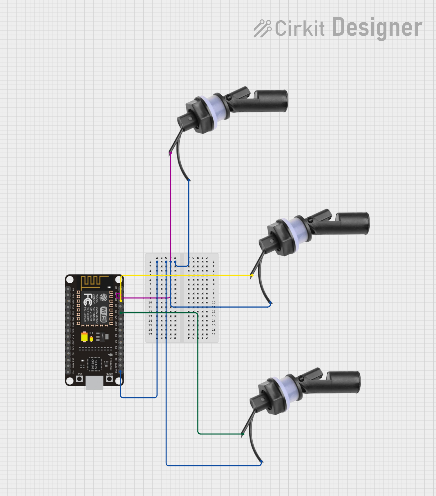
This circuit is designed to monitor water levels using multiple Water Level Float Switch Sensors and an ESP8266 NodeMCU microcontroller. The ESP8266 NodeMCU is responsible for reading the status of the float switches and can be programmed to take action when certain water levels are detected. The float switches are connected to the digital input pins of the ESP8266 NodeMCU, and the 3V3 pin of the microcontroller provides power to the switches.
Component List
Water Level Float Switch Sensor
- Description: A sensor used to detect the level of water in a tank or container.
- Pins: Wire1, Wire2
- Purpose: To signal the microcontroller when the water reaches a certain level.
ESP8266 NodeMCU
- Description: A Wi-Fi enabled microcontroller module with an ESP8266 chip.
- Pins: D0, D1, D2, D3, D4, 3V3, GND, D5, D6, D7, D8, RX, TX, A0, RSV, SD3, SD2, SD1, CMD, SD0, CLK, EN, RST, VIN
- Purpose: To process the signals from the water level sensors and perform actions such as sending alerts or controlling other devices.
Wiring Details
Water Level Float Switch Sensors
- Sensor 1:
- Wire1: Connected to ESP8266 NodeMCU pin D1
- Wire2: Connected to ESP8266 NodeMCU pin 3V3 (Power)
- Sensor 2:
- Wire1: Connected to ESP8266 NodeMCU pin D2
- Wire2: Connected to ESP8266 NodeMCU pin 3V3 (Power)
- Sensor 3:
- Wire1: Connected to ESP8266 NodeMCU pin D4
- Wire2: Connected to ESP8266 NodeMCU pin 3V3 (Power)
ESP8266 NodeMCU
- Power Supply:
- 3V3: Connected to Wire2 of all Water Level Float Switch Sensors
- Digital Inputs:
- D1: Connected to Wire1 of Sensor 1
- D2: Connected to Wire1 of Sensor 2
- D4: Connected to Wire1 of Sensor 3
- Ground:
- GND: Not connected in the provided net list (should be connected to a common ground if necessary)
Documented Code
No code was provided for the microcontroller. The ESP8266 NodeMCU should be programmed to read the digital inputs connected to the water level sensors and take appropriate actions based on the sensor states. The code would typically include setup routines for configuring the GPIO pins as inputs, a loop function for continuously checking the sensor states, and possibly communication routines for sending data to a server or user interface.