
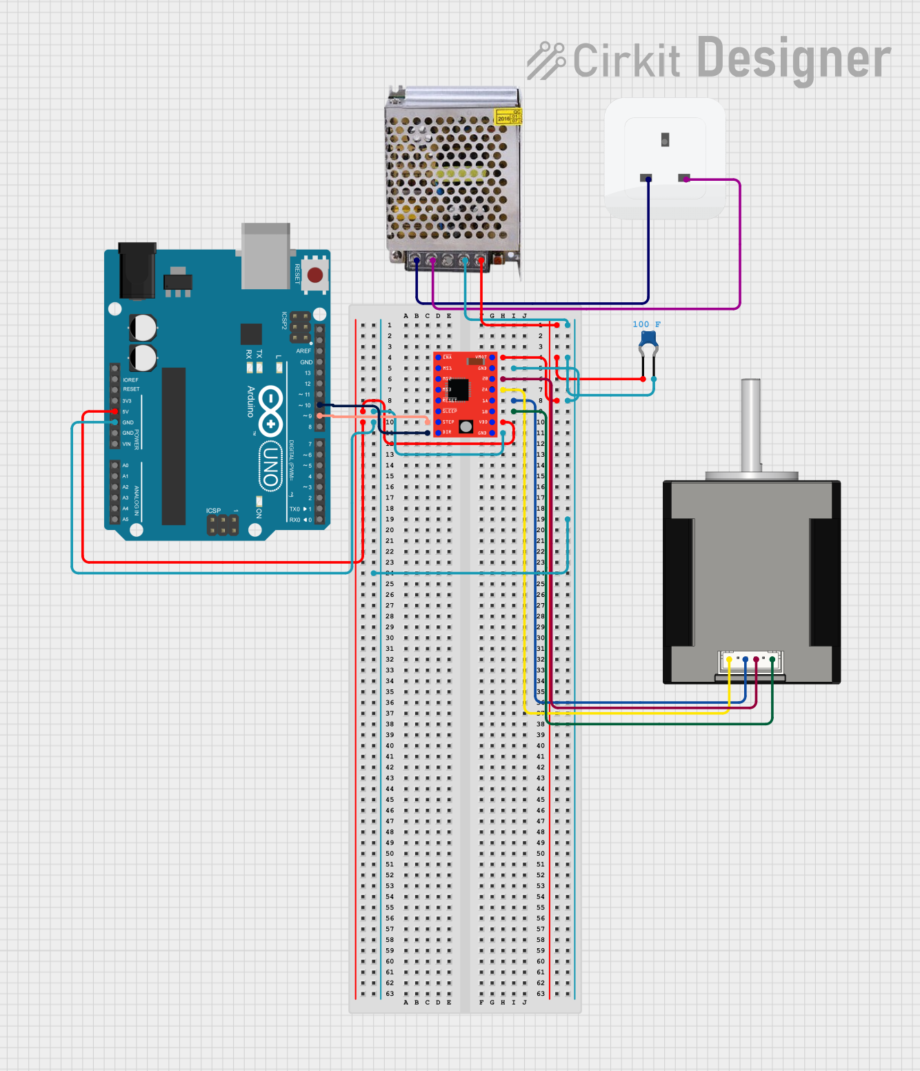
Circuit Documentation
Summary
This document provides a detailed overview of a circuit designed to control a Nema 17 stepper motor using an A4988 stepper motor driver and an Arduino UNO. The circuit is powered by a 5V 5A power supply and includes a ceramic capacitor for noise filtering. The Arduino UNO is programmed to control the stepper motor through the A4988 driver.
Component List
Nema 17 42-STH48 Stepper Motor
- Pins: A2 (black), A1 (Green), B2 (Red), B1 (Blue)
- Description: Stepper motor used for precise control of rotational position.
A4988 Stepper Motor Driver (Red)
- Pins: ENABLE, MS1, MS2, MS3, RESET, SLEEP, STEP, DIR, VMOT, GND, 2B, 2A, 1A, 1B, VDD
- Description: Driver module for controlling the stepper motor.
POWER SUPPLY 5V 5AMP
- Pins: 220V Positive Pole (AC), 220V Negative Pole (AC), GND, GND (DC), 12V-24V Output (DC)
- Description: Power supply unit providing 5V and 5A output.
Socket
- Pins: earth, life, neutral
- Description: Standard electrical socket for AC power input.
Ceramic Capacitor
- Pins: pin0, pin1
- Description: Capacitor used for noise filtering.
- Properties: Capacitance = 100 Farads
Arduino UNO
- Pins: UNUSED, IOREF, Reset, 3.3V, 5V, GND, Vin, A0, A1, A2, A3, A4, A5, SCL, SDA, AREF, D13, D12, D11, D10, D9, D8, D7, D6, D5, D4, D3, D2, D1, D0
- Description: Microcontroller board used for controlling the stepper motor driver.
Wiring Details
Nema 17 42-STH48 Stepper Motor
- A2 (black) connected to 2A on A4988 Stepper Motor Driver (Red)
- A1 (Green) connected to 1A on A4988 Stepper Motor Driver (Red)
- B2 (Red) connected to 2B on A4988 Stepper Motor Driver (Red)
- B1 (Blue) connected to 1B on A4988 Stepper Motor Driver (Red)
A4988 Stepper Motor Driver (Red)
- 2A connected to A2 (black) on Nema 17 42-STH48 Stepper Motor
- 1A connected to A1 (Green) on Nema 17 42-STH48 Stepper Motor
- 2B connected to B2 (Red) on Nema 17 42-STH48 Stepper Motor
- 1B connected to B1 (Blue) on Nema 17 42-STH48 Stepper Motor
- VMOT connected to 12V-24V Output (DC) on POWER SUPPLY 5V 5AMP
- GND connected to GND (DC) on POWER SUPPLY 5V 5AMP
- GND connected to GND (DC) on POWER SUPPLY 5V 5AMP
- GND connected to GND on Arduino UNO
- VDD connected to 5V on Arduino UNO
- STEP connected to D9 on Arduino UNO
- DIR connected to D10 on Arduino UNO
POWER SUPPLY 5V 5AMP
- 12V-24V Output (DC) connected to VMOT on A4988 Stepper Motor Driver (Red)
- GND (DC) connected to GND on A4988 Stepper Motor Driver (Red)
- GND (DC) connected to GND on A4988 Stepper Motor Driver (Red)
- GND (DC) connected to GND on Arduino UNO
- 220V Positive Pole (AC) connected to life on Socket
- 220V Negative Pole (AC) connected to neutral on Socket
Socket
- life connected to 220V Positive Pole (AC) on POWER SUPPLY 5V 5AMP
- neutral connected to 220V Negative Pole (AC) on POWER SUPPLY 5V 5AMP
Ceramic Capacitor
- pin0 connected to 12V-24V Output (DC) on POWER SUPPLY 5V 5AMP
- pin1 connected to GND (DC) on POWER SUPPLY 5V 5AMP
Arduino UNO
- GND connected to GND (DC) on POWER SUPPLY 5V 5AMP
- 5V connected to VDD on A4988 Stepper Motor Driver (Red)
- D9 connected to STEP on A4988 Stepper Motor Driver (Red)
- D10 connected to DIR on A4988 Stepper Motor Driver (Red)
Documented Code
Arduino UNO Code (sketch.ino)
void setup() {
  // put your setup code here, to run once:

}

void loop() {
  // put your main code here, to run repeatedly:

}
Additional Documentation (documentation.txt)
This document provides a comprehensive overview of the circuit, including a detailed component list, wiring details, and the code used for the Arduino UNO.