Arduino UNO-Based Noise Cancellation System with Dual KY-037 Microphones and Op-Amp
Circuit Documentation
Summary
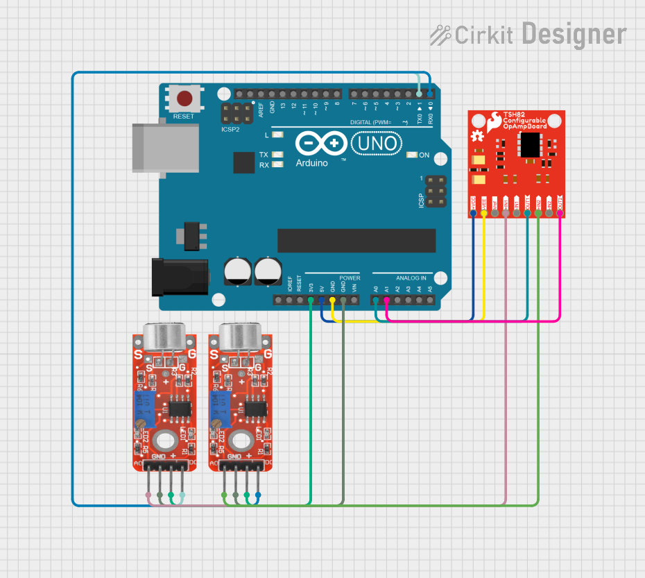
This circuit is designed to read analog signals from two KY-037 microphones, process them through a Sparkfun Configurable OpAmp Board (TSH82), and perform basic noise cancellation using an Arduino UNO. The processed signal is then printed to the Serial Monitor. This setup is a basic example and does not represent a true adaptive filter. For effective noise cancellation, a more sophisticated algorithm like the Least Mean Squares (LMS) algorithm should be implemented.
Component List
Arduino UNO
- Description: A microcontroller board based on the ATmega328P.
- Pins: UNUSED, IOREF, Reset, 3.3V, 5V, GND, Vin, A0, A1, A2, A3, A4, A5, SCL, SDA, AREF, D13, D12, D11, D10, D9, D8, D7, D6, D5, D4, D3, D2, D1, D0
KY-037 Microphone (Primary)
- Description: A microphone sensor module with both analog and digital outputs.
- Pins: Analog output, Ground, VCC, Digital output
KY-037 Microphone (Reference)
- Description: A microphone sensor module with both analog and digital outputs.
- Pins: Analog output, Ground, VCC, Digital output
Sparkfun Configurable OpAmp Board - TSH82
- Description: An operational amplifier board that can be configured for various applications.
- Pins: VCC, VNEG, VREF, +IN1, OUT1, -IN1, +IN2, -IN2, OUT2
Wiring Details
Arduino UNO
3.3V connected to:
- KY-037 Microphone (Primary) VCC
- KY-037 Microphone (Reference) VCC
5V connected to:
- Sparkfun Configurable OpAmp Board - TSH82 VCC
GND connected to:
- KY-037 Microphone (Primary) Ground
- KY-037 Microphone (Reference) Ground
- Sparkfun Configurable OpAmp Board - TSH82 VNEG
A0 connected to:
- Sparkfun Configurable OpAmp Board - TSH82 OUT1
A1 connected to:
- Sparkfun Configurable OpAmp Board - TSH82 OUT2
D1 connected to:
- KY-037 Microphone (Primary) Digital output
D0 connected to:
- KY-037 Microphone (Reference) Digital output
KY-037 Microphone (Primary)
VCC connected to:
- Arduino UNO 3.3V
Ground connected to:
- Arduino UNO GND
Analog output connected to:
- Sparkfun Configurable OpAmp Board - TSH82 +IN1
Digital output connected to:
- Arduino UNO D1
KY-037 Microphone (Reference)
VCC connected to:
- Arduino UNO 3.3V
Ground connected to:
- Arduino UNO GND
Analog output connected to:
- Sparkfun Configurable OpAmp Board - TSH82 +IN2
Digital output connected to:
- Arduino UNO D0
Sparkfun Configurable OpAmp Board - TSH82
VCC connected to:
- Arduino UNO 5V
VNEG connected to:
- Arduino UNO GND
OUT1 connected to:
- Arduino UNO A0
OUT2 connected to:
- Arduino UNO A1
+IN1 connected to:
- KY-037 Microphone (Primary) Analog output
+IN2 connected to:
- KY-037 Microphone (Reference) Analog output
Code Documentation
/*
 * This Arduino sketch reads analog signals from two KY-037 microphones,
 * processes them through an op-amp, and attempts a basic noise cancellation
 * by subtracting the reference signal from the primary signal. The result is
 * printed to the Serial Monitor. This is a basic example and does not represent
 * a true adaptive filter. For effective noise cancellation, a more sophisticated
 * algorithm like the Least Mean Squares (LMS) algorithm should be implemented.
 */

const int mic1Pin = A0; // Primary microphone signal
const int mic2Pin = A1; // Reference microphone signal
const int mic1DigitalPin = 1; // Digital output from primary mic
const int mic2DigitalPin = 0; // Digital output from reference mic

void setup() {
    Serial.begin(9600); // Initialize serial communication at 9600 baud
    pinMode(mic1DigitalPin, INPUT); // Set digital pin for primary mic as input
    pinMode(mic2DigitalPin, INPUT); // Set digital pin for reference mic as input
}

void loop() {
    int primarySignal = analogRead(mic1Pin); // Read primary mic analog signal
    int referenceSignal = analogRead(mic2Pin); // Read reference mic analog signal

    // Basic noise cancellation by subtracting reference from primary signal
    int filteredSignal = primarySignal - referenceSignal;

    // Print the filtered signal to the Serial Monitor
    Serial.println(filteredSignal);
    delay(10); // Short delay for stability
}
This code initializes the Arduino UNO to read analog signals from two KY-037 microphones and perform basic noise cancellation by subtracting the reference signal from the primary signal. The filtered signal is then printed to the Serial Monitor.