
Raspberry Pi-Controlled Weight Measurement and Object Detection System with Actuation and Motion Control
View and Edit Project In Cirkit Designer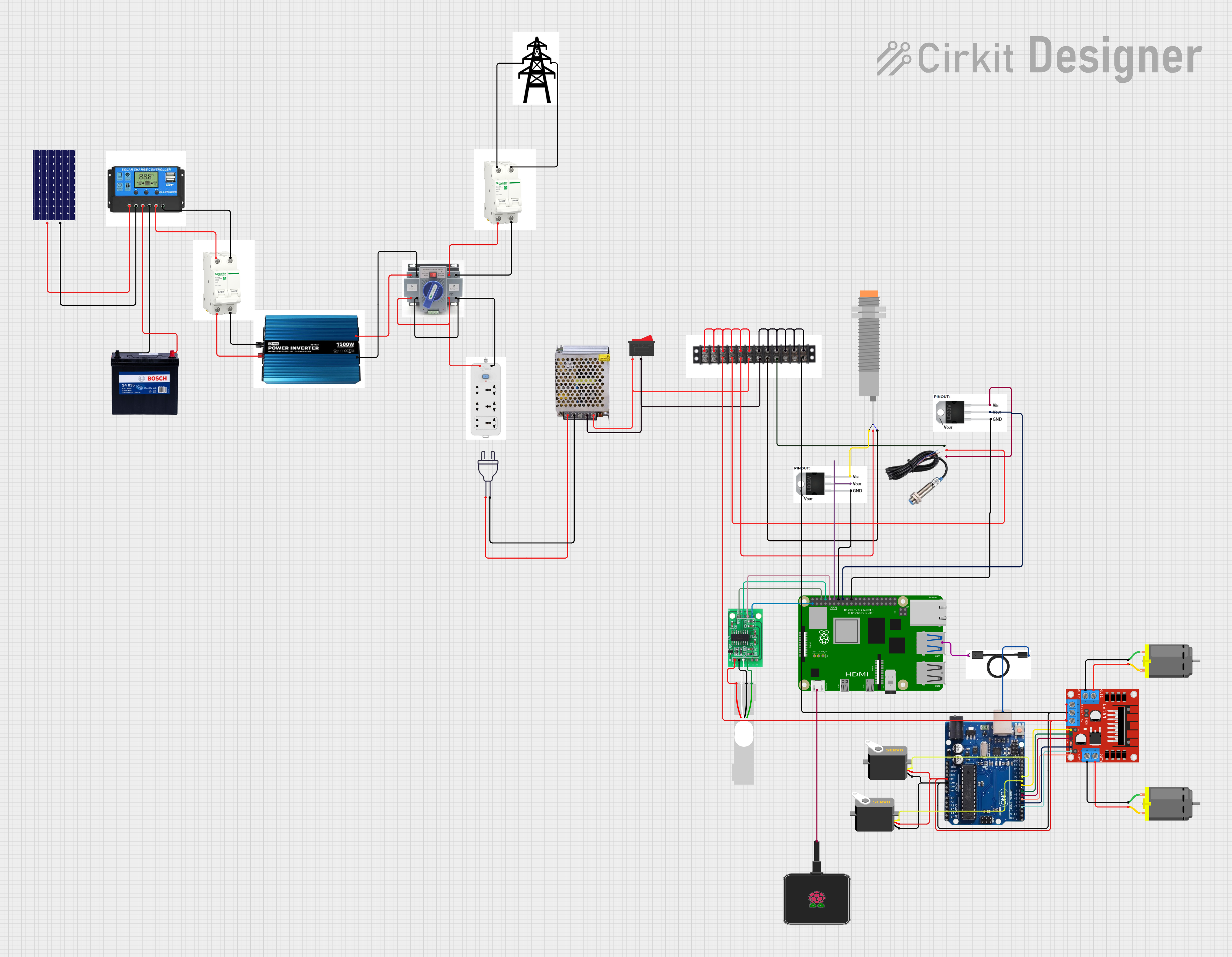
Circuit Documentation
Summary
The circuit in question appears to be a complex system involving various sensors, actuators, a microcontroller (Arduino Uno R3), a single-board computer (Raspberry Pi 4B), power management components, and motor drivers. The system is designed to interface with a load cell using an HX711 bridge sensor interface, control servos and DC motors, and manage power through a combination of a solar panel, charge controller, and battery. The circuit also includes safety and control elements such as a rocker switch, breakers, and an ATS (Automatic Transfer Switch).
Component List
HX711 - Bridge Sensor Interface
- A precision 24-bit analog-to-digital converter (ADC) designed for weigh scales and industrial control applications to interface directly with a bridge sensor.
Load Cell - Red/white/black/green
- A type of transducer that is used to create an electrical signal whose magnitude is directly proportional to the force being measured.
LJ18A3-H-ZBX Inductive Proximity Sensor
- A non-contact sensor used to detect the presence of metal objects.
Inductive Sensor
- Another type of non-contact sensor that detects metallic objects without requiring physical contact.
Arduino Uno R3
- A microcontroller board based on the ATmega328P, with digital input/output pins, analog inputs, and various other features for building electronic projects.
Servo (2 instances)
- A rotary actuator or linear actuator that allows for precise control of angular or linear position, velocity, and acceleration.
Raspberry Pi 4B
- A small single-board computer with a broad set of GPIO pins, capable of performing various computing tasks.
Rocker Switch
- An on-off electrical switch that rocks (rather than trips) when pressed.
DC Motor (2 instances)
- An electric motor that runs on direct current electricity.
POWER SUPPLY 12V 5AMP
- A power supply unit that provides 12V and up to 5A of current, suitable for powering various components in the circuit.
power 220v
- Represents the main AC power source, typically at 220V.
Terminal Block
- A modular, insulated block that secures two or more wires together.
USB-C to Laptop
- A cable used to connect USB-C devices to a laptop, likely for programming or power.
L298N DC motor driver
- A high-power motor driver capable of driving up to two DC motors.
ld1117v33 voltage regulator (2 instances)
- A low-dropout voltage regulator that provides a fixed output voltage with a low dropout voltage and output current up to 800mA.
Raspberry pi power supply
- A dedicated power supply for the Raspberry Pi, providing the necessary voltage and current for stable operation.
Transmission Tower
- Likely a representation of a communication tower in the system, possibly for wireless data transmission.
Inverter
- A power electronic device or circuitry that changes direct current (DC) to alternating current (AC).
breaker (2 instances)
- An automatic electrical switch designed to protect an electrical circuit from damage caused by overload or short circuit.
solar panel
- A panel designed to absorb the sun's rays as a source of energy for generating electricity.
ATS (Automatic Transfer Switch)
- An electrical switch that switches a load between two sources, such as between mains power and emergency power.
Charge Controller
- A device that regulates the voltage and current coming from the solar panels going to the battery.
12V 200Ah Battery
- A rechargeable battery with a voltage of 12V and a capacity of 200Ah, used for energy storage.
Extension
- Likely a representation of an extension of the circuit or additional functionality.
Wiring Details
HX711 - Bridge Sensor Interface
- E+, E-, A-, A+ connected to corresponding pins on Load Cell.
- GND connected to Raspberry Pi 4B GND.
- DATA (OUT) connected to Raspberry Pi 4B GPIO14.
- SCK - CLOCK (IN) connected to Raspberry Pi 4B GPIO15.
- 3.3/3.5V Supply connected to Raspberry Pi 4B 3V3.
Load Cell - Red/white/black/green
- E+, E-, A-, A+ connected to corresponding pins on HX711.
LJ18A3-H-ZBX Inductive Proximity Sensor
- VO (BLU) connected to Terminal Block -.
- VI (BRN) connected to Terminal Block +.
- SIG (BLK) connected to ld1117v33 voltage regulator.
Inductive Sensor
- Signal connected to ld1117v33 voltage regulator.
- VCC connected to Terminal Block +.
- GND connected to Terminal Block -.
Arduino Uno R3
- USB Port connected to USB-C to Laptop USB-C.
- 5V connected to Servos vcc and L298N DC motor driver 5V.
- GND connected to Servos gnd, L298N DC motor driver GND, and Terminal Block -.
- Digital pins 10, 9, 8, 7, 6, 5, 4, 3 connected to Servos pulse and L298N DC motor driver ENA, IN1, IN2, IN3, IN4, ENB respectively.
Servo (2 instances)
- vcc connected to Arduino Uno R3 5V.
- gnd connected to Arduino Uno R3 GND.
- pulse connected to Arduino Uno R3 digital pins 10 and 9.
Raspberry Pi 4B
- GND connected to various components including HX711, ld1117v33 voltage regulators, and Raspberry pi power supply.
- GPIO14, GPIO15 connected to HX711 DATA (OUT) and SCK - CLOCK (IN).
- 3V3 connected to HX711 3.3/3.5V Supply.
- GPIO18, GPIO23 connected to ld1117v33 voltage regulators.
- Connected to Raspberry pi power supply and USB-C to Laptop USB-A.
Rocker Switch
- Pin 1 connected to Terminal Block + and POWER SUPPLY 12V 5AMP 12V-24V Output (DC).
- Pin 2 connected to Terminal Block - and POWER SUPPLY 12V 5AMP GND (DC).
DC Motor (2 instances)
- Pin 1 connected to L298N DC motor driver OUT3 and OUT2.
- Pin 2 connected to L298N DC motor driver OUT4 and OUT1.
POWER SUPPLY 12V 5AMP
- 220V Positive Pole (AC) connected to power 220v hot wire.
- 220V Negative Pole (AC) connected to power 220v neutral wire.
- GND (DC) connected to Terminal Block - and Rocker Switch pin 2.
- 12V-24V Output (DC) connected to Terminal Block + and Rocker Switch pin 1.
ld1117v33 voltage regulator (2 instances)
- Connected to Raspberry Pi 4B GPIO18, GPIO23 for input and GND. Outputs are connected to LJ18A3-H-ZBX Inductive Proximity Sensor SIG (BLK) and Inductive Sensor Signal.
Transmission Tower
- VCC connected to breaker VCC.
- GND connected to breaker GND.
Inverter
- GND connected to breaker GND.
- VCC connected to breaker VCC.
breaker (2 instances)
- VCC and GND connected between Transmission Tower, Inverter, ATS, and Charge Controller.
solar panel
-
- connected to Charge Controller Solar Positive.
-
- connected to Charge Controller Solar Negative.
ATS (Automatic Transfer Switch)
-
- and - connected to Inverter VCC and GND.
-
- and - connected to breaker VCC and GND.
-
- and - connected to Extension + and -.
Charge Controller
- Load Positive and Load Negative connected to breaker VCC and GND.
- Battery Positive and Battery Negative connected to 12V 200Ah Battery 12V and GND.
- Solar Positive and Solar Negative connected to solar panel + and -.
12V 200Ah Battery
- 12V connected to Charge Controller Battery Positive.
- GND connected to Charge Controller Battery Negative.
Extension
-
- and - connected to ATS + and -.
Documented Code
No code was provided for the microcontrollers in the circuit. If code is available, it should be documented here with explanations for each function and how it interacts with the connected hardware components.