
LM317 Voltage Regulator Circuit with Bridge Rectifier for Stable DC Output
View and Edit Project In Cirkit Designer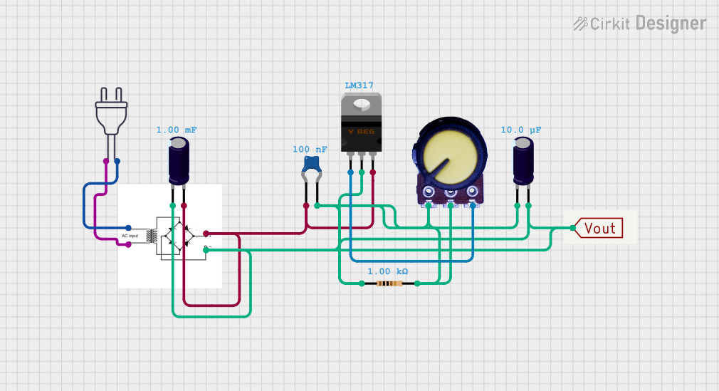
Circuit Documentation
Summary
This document provides a detailed overview of a power supply circuit. The circuit converts 220V AC to a regulated DC voltage using a bridge rectifier, capacitors, a voltage regulator, and other passive components. The document includes a component list, wiring details, and code (if applicable).
Component List
Bridge Rectifier
- Description: Converts AC input to DC output.
- Pins: AC input +, AC input -, +, -
Power 220V
- Description: Provides 220V AC power.
- Pins: Hot wire, Neutral wire
Electrolytic Capacitor (0.001 Farads)
- Description: Smooths the rectified DC voltage.
- Pins: +, -
Ceramic Capacitor (100nF)
- Description: Filters high-frequency noise.
- Pins: pin0, pin1
LM317 Voltage Regulator
- Description: Regulates the output voltage.
- Pins: Adj, V_out, V_in
Resistor (1k Ohms)
- Description: Sets the output voltage of the LM317.
- Pins: pin1, pin2
Potentiometer
- Description: Adjustable resistor for fine-tuning the output voltage.
- Pins: GND, Output, VCC
Electrolytic Capacitor (10uF)
- Description: Further smooths the output voltage.
- Pins: +, -
Vout
- Description: Output terminal for the regulated DC voltage.
- Pins: Vout
Wiring Details
Bridge Rectifier
- AC input + is connected to Neutral wire of Power 220V.
- AC input - is connected to Hot wire of Power 220V.
- + is connected to:
- V_in of LM317 Voltage Regulator
- + of Electrolytic Capacitor (0.001 Farads)
- pin0 of Ceramic Capacitor (100nF)
- - is connected to:
- - of Electrolytic Capacitor (0.001 Farads)
- - of Electrolytic Capacitor (10uF)
- pin1 of Ceramic Capacitor (100nF)
Power 220V
- Hot wire is connected to AC input - of Bridge Rectifier.
- Neutral wire is connected to AC input + of Bridge Rectifier.
Electrolytic Capacitor (0.001 Farads)
- + is connected to:
- V_in of LM317 Voltage Regulator
- + of Bridge Rectifier
- pin0 of Ceramic Capacitor (100nF)
- - is connected to:
- - of Bridge Rectifier
- - of Electrolytic Capacitor (10uF)
- pin1 of Ceramic Capacitor (100nF)
Ceramic Capacitor (100nF)
- pin0 is connected to:
- V_in of LM317 Voltage Regulator
- + of Electrolytic Capacitor (0.001 Farads)
- + of Bridge Rectifier
- pin1 is connected to:
- - of Bridge Rectifier
- - of Electrolytic Capacitor (0.001 Farads)
- - of Electrolytic Capacitor (10uF)
LM317 Voltage Regulator
- V_in is connected to:
- + of Bridge Rectifier
- + of Electrolytic Capacitor (0.001 Farads)
- pin0 of Ceramic Capacitor (100nF)
- V_out is connected to:
- pin1 of Resistor (1k Ohms)
- pin2 of Resistor (1k Ohms)
- GND of Potentiometer
- Output of Potentiometer
- Vout of Vout
- - of Electrolytic Capacitor (0.001 Farads)
- - of Electrolytic Capacitor (10uF)
- pin1 of Ceramic Capacitor (100nF)
- Adj is connected to VCC of Potentiometer.
Resistor (1k Ohms)
- pin1 is connected to V_out of LM317 Voltage Regulator.
- pin2 is connected to V_out of LM317 Voltage Regulator.
Potentiometer
- GND is connected to V_out of LM317 Voltage Regulator.
- Output is connected to V_out of LM317 Voltage Regulator.
- VCC is connected to Adj of LM317 Voltage Regulator.
Electrolytic Capacitor (10uF)
- + is connected to V_out of LM317 Voltage Regulator.
- - is connected to:
- - of Bridge Rectifier
- - of Electrolytic Capacitor (0.001 Farads)
- pin1 of Ceramic Capacitor (100nF)
Vout
- Vout is connected to V_out of LM317 Voltage Regulator.
Code
No microcontroller code is present in this circuit.
This document provides a comprehensive overview of the circuit, including a detailed component list and wiring details. If you have any questions or need further assistance, please feel free to ask.