
Arduino UNO Controlled Water Level Indicator with Bluetooth Connectivity
View and Edit Project In Cirkit Designer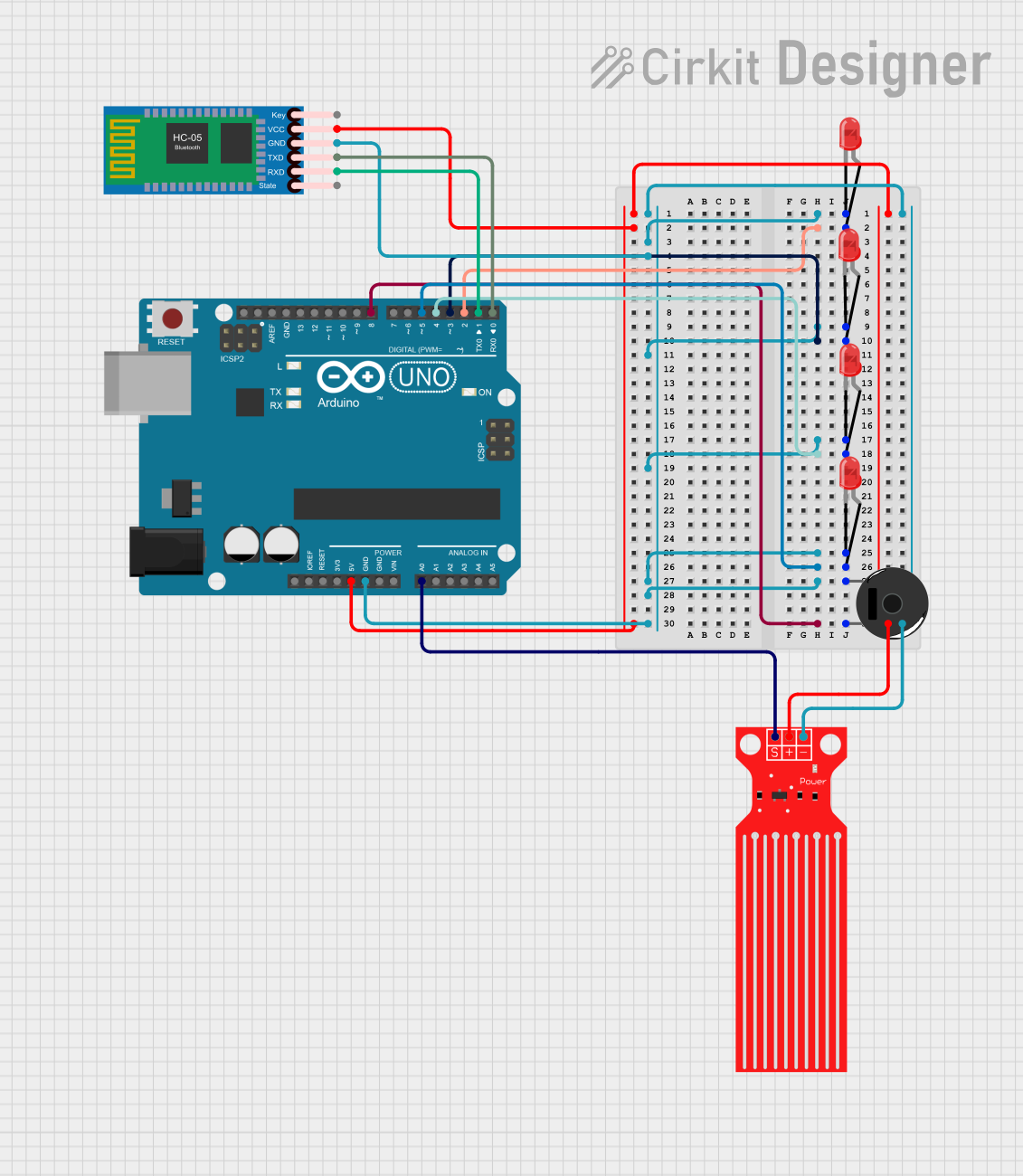
Circuit Documentation
Summary of the Circuit
This circuit is designed to interface an Arduino UNO with a series of LEDs, a water level sensor, a piezo buzzer, and an HC-05 Bluetooth module. The Arduino UNO acts as the central controller, managing the inputs and outputs of the circuit. The LEDs are used as indicators, the water level sensor monitors the level of water, the piezo buzzer can provide audio alerts, and the HC-05 Bluetooth module enables wireless communication.
Component List
Arduino UNO
- Description: A microcontroller board based on the ATmega328P.
- Purpose: Acts as the central processing unit of the circuit, controlling the LEDs, reading the water level sensor, driving the piezo buzzer, and communicating with the HC-05 Bluetooth module.
LED: Two Pin (red)
- Description: A basic red LED with an anode and cathode pin.
- Purpose: Serves as an indicator light in the circuit.
Water Level Sensor
- Description: A sensor that detects the level of water.
- Purpose: Provides water level data to the Arduino UNO for processing.
Piezo Buzzer
- Description: An electronic device that emits sound when an electric current is applied.
- Purpose: Generates audio signals under the control of the Arduino UNO.
HC-05 Bluetooth Module
- Description: A wireless communication module that enables Bluetooth connectivity.
- Purpose: Allows the Arduino UNO to communicate with other Bluetooth-enabled devices.
Wiring Details
Arduino UNO
- 5V: Provides power to the HC-05 Bluetooth Module and the Water Level Sensor.
- GND: Common ground for the HC-05 Bluetooth Module, Water Level Sensor, Piezo Buzzer, and all LEDs.
- D0 (RX): Receives data from the HC-05 Bluetooth Module's TXD pin.
- D1 (TX): Sends data to the HC-05 Bluetooth Module's RXD pin.
- D2-D5: Control the anodes of the red LEDs.
- D8: Controls the Piezo Buzzer.
- A0: Reads the signal from the Water Level Sensor.
LED: Two Pin (red)
- Anode: Connected to individual digital pins (D2-D5) on the Arduino UNO for control.
- Cathode: Connected to the common ground.
Water Level Sensor
- SIG: Connected to the A0 pin on the Arduino UNO for signal reading.
- VCC: Powered by the 5V pin on the Arduino UNO.
- GND: Connected to the common ground.
Piezo Buzzer
- Pin 1: Connected to the common ground.
- Pin 2: Controlled by the D8 pin on the Arduino UNO.
HC-05 Bluetooth Module
- VCC: Powered by the 5V pin on the Arduino UNO.
- GND: Connected to the common ground.
- TXD: Sends data to the D0 (RX) pin on the Arduino UNO.
- RXD: Receives data from the D1 (TX) pin on the Arduino UNO.
Documented Code
Arduino UNO Code (sketch.ino)
void setup() {
  // put your setup code here, to run once:

}

void loop() {
  // put your main code here, to run repeatedly:

}
The provided code is a template with empty setup() and loop() functions. The setup() function is intended for initialization code that runs once at the start, such as pin mode declarations. The loop() function contains the main logic that the Arduino will execute repeatedly.
Additional Notes
- The code for the Arduino UNO is currently a placeholder and needs to be populated with the logic to control the LEDs, read the water level sensor, drive the piezo buzzer, and handle Bluetooth communication with the HC-05 module.
- The
documentation.txtfile is empty and can be used to add further explanations, usage instructions, or any additional information relevant to the operation or maintenance of the circuit.