Cirkit Designer
Your all-in-one circuit design IDE
Home /
Project Documentation
74HC Logic Gate Array with Battery Power

Circuit Documentation
Summary
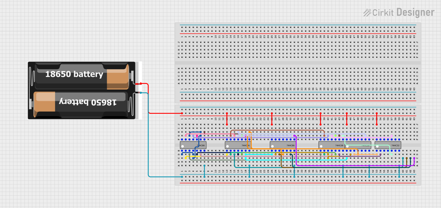
The circuit in question appears to be a digital logic circuit utilizing a combination of 74HC series logic gates. These gates include the 74HC08 (AND gate), 74HC86 (XOR gate), and 74HC32 (OR gate), along with a power source provided by 2x 18650 batteries. The circuit's functionality is not explicitly stated, but it likely performs a specific logic operation based on the interconnections of the gates. There is no microcontroller code provided, indicating that the circuit operates purely on combinational logic.
Component List
2x 18650 Batteries
- Description: A pair of 18650 lithium-ion rechargeable batteries.
- Pins:
vcc,gnd
74HC08 Quad 2-input AND Gate
- Description: A quad 2-input AND gate IC.
- Pins:
A1,B1,Y1,A2,B2,Y2,GND,VCC,A3,B3,Y3,A4,B4,Y4
74HC86 Quad 2-input XOR Gate
- Description: A quad 2-input exclusive OR gate IC.
- Pins:
A1,B1,Y1,A2,B2,Y2,GND,VCC,A3,B3,Y3,A4,B4,Y4
74HC32 Quad 2-input OR Gate
- Description: A quad 2-input OR gate IC.
- Pins:
A1,B1,Y1,A2,B2,Y2,GND,VCC,A3,B3,Y3,A4,B4,Y4
Wiring Details
2x 18650 Batteries
vccconnected to VCC of all ICsgndconnected to GND of all ICs
74HC08 Quad 2-input AND Gate
- Inputs (
A1,B1,A2,B2,A3,B3,A4,B4) connected to various outputs of 74HC86 XOR gates or other 74HC08 AND gates. - Outputs (
Y1,Y2,Y3,Y4) connected to inputs of 74HC32 OR gates or other 74HC08 AND gates. GNDandVCCconnected to the power source.
74HC86 Quad 2-input XOR Gate
- Inputs (
A1,B1,A2,B2,A3,B3,A4,B4) connected to various outputs of other 74HC86 XOR gates, 74HC08 AND gates, or 74HC32 OR gates. - Outputs (
Y1,Y2,Y3,Y4) connected to inputs of 74HC08 AND gates or other 74HC86 XOR gates. GNDandVCCconnected to the power source.
74HC32 Quad 2-input OR Gate
- Inputs (
A1,B1,A2,B2,A3,B3,A4,B4) connected to outputs of 74HC08 AND gates or other 74HC32 OR gates. - Outputs (
Y1,Y2,Y3,Y4) connected to inputs of 74HC86 XOR gates or other 74HC32 OR gates. GNDandVCCconnected to the power source.
Documented Code
No microcontroller code has been provided for this circuit. The circuit operates based on the logic provided by the interconnected logic gates without the need for programmable devices or embedded code.