Cirkit Designer
Your all-in-one circuit design IDE
Home /
Project Documentation
Arduino UNO Controlled Solenoid Door Lock with Keypad Interface
Circuit Documentation
Summary of the Circuit
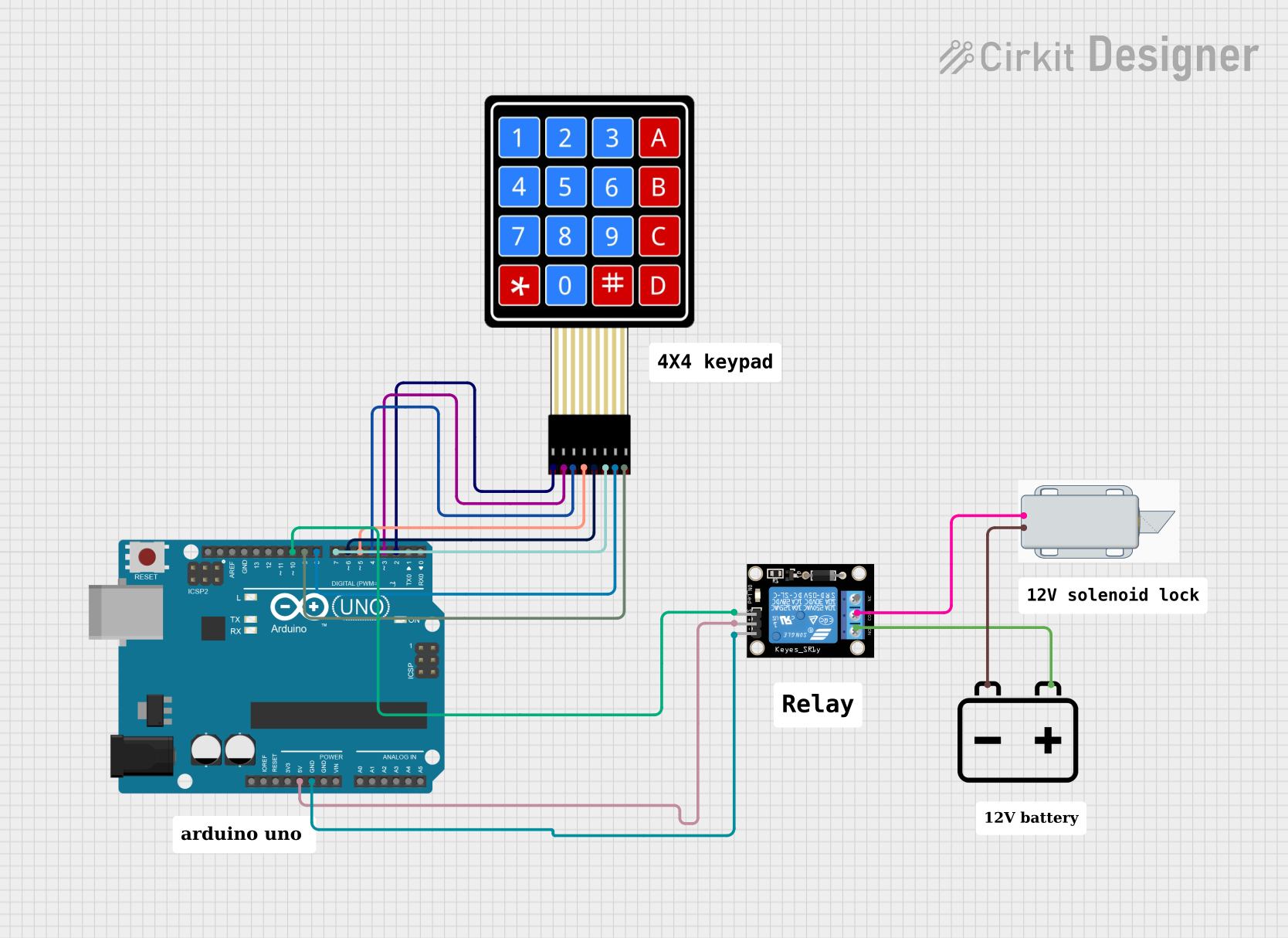
This circuit is designed to interface an Arduino UNO with a 4x4 membrane matrix keypad and control a 12V solenoid lock using a relay module. The solenoid lock is powered by a 12V battery. The Arduino UNO is responsible for processing the input from the keypad and activating the relay, which in turn controls the power to the solenoid lock.
Component List
Arduino UNO
- Microcontroller board based on the ATmega328P
- It has 14 digital input/output pins, 6 analog inputs, a 16 MHz quartz crystal, a USB connection, a power jack, an ICSP header, and a reset button.
12V Battery
- Provides the power source for the solenoid lock.
4X4 Membrane Matrix Keypad
- A 16-button keypad that provides user input to the microcontroller.
Relay Module 1 Channel
- An electrically operated switch that allows the Arduino to control higher power devices, like the 12V solenoid lock.
12V Solenoid Lock
- An electromechanical lock that can be controlled via the relay to lock or unlock.
Wiring Details
Arduino UNO
5VandGNDare used to power the relay module.- Digital pins
D2toD10are used to interface with the 4x4 keypad and the relay module.
12V Battery
- The
+terminal is connected to theNO(Normally Open) terminal of the relay module and the+terminal of the solenoid lock. - The
-terminal is connected to the-terminal of the solenoid lock.
4X4 Membrane Matrix Keypad
- The row pins
R1toR4are connected to Arduino digital pinsD2toD5. - The column pins
C1toC4are connected to Arduino digital pinsD6toD9.
Relay Module 1 Channel
- The
S(Signal) pin is connected to Arduino digital pinD10. - The
5VandGNDpins are connected to the corresponding power supply pins on the Arduino. - The
COM(Common) pin is connected to the-terminal of the solenoid lock. - The
NO(Normally Open) pin is connected to the+terminal of the 12V battery.
12V Solenoid Lock
- The
+terminal is connected to theNOterminal of the relay module. - The
-terminal is connected to theCOMterminal of the relay module and the-terminal of the 12V battery.
Documented Code
Arduino Sketch (sketch.ino)
void setup() {
  // put your setup code here, to run once:

}

void loop() {
  // put your main code here, to run repeatedly:

}
Additional Documentation (documentation.txt)
No additional code documentation was provided.