
Arduino UNO Solar Panel Efficiency Monitoring System with Current, Voltage, Light, and Temperature Sensors
View and Edit Project In Cirkit Designer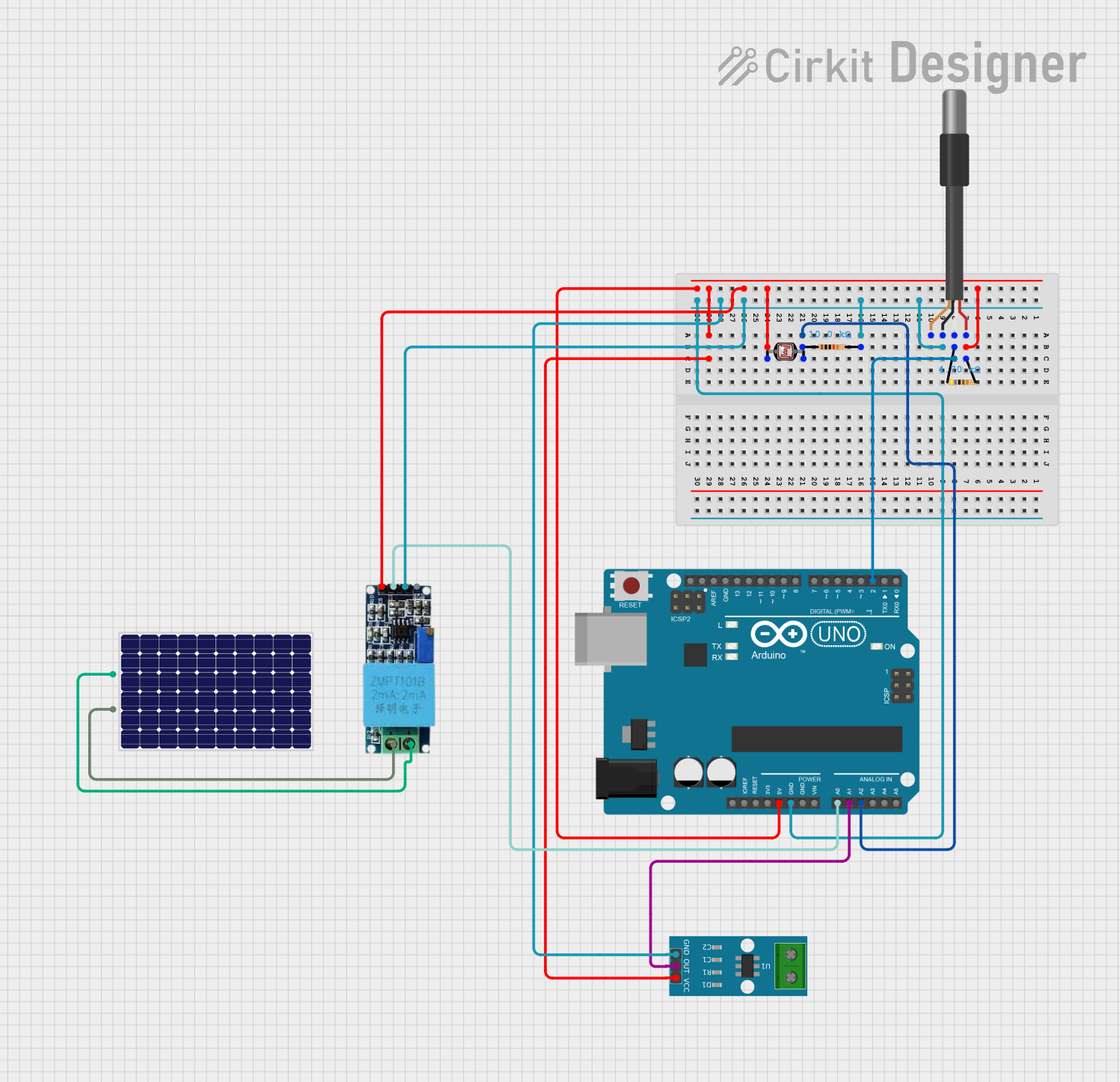
Solar Panel Efficiency Monitoring System
Summary
This circuit is designed to monitor the efficiency of a solar panel by measuring voltage, current, light intensity, and temperature. The data is collected using various sensors and processed by an Arduino UNO microcontroller. The results are displayed on the serial monitor.
Component List
Arduino UNO
- Description: A microcontroller board based on the ATmega328P.
- Pins: UNUSED, IOREF, Reset, 3.3V, 5V, GND, Vin, A0, A1, A2, A3, A4, A5, SCL, SDA, AREF, D13, D12, D11, D10, D9, D8, D7, D6, D5, D4, D3, D2, D1, D0
ACS712 Current Sensor 5A 20A 30A
- Description: A current sensor that provides an analog voltage output proportional to the current passing through it.
- Pins: 1, 2, GND, OUT, VCC
Photocell (LDR)
- Description: A light-dependent resistor that changes its resistance based on the light intensity.
- Pins: pin 0, pin 1
Resistor (10k Ohms)
- Description: A resistor with a resistance of 10k Ohms.
- Pins: pin1, pin2
Voltage Sensor
- Description: A sensor that measures voltage and provides an analog output.
- Pins: Ground, Phase, Vcc, Out, Gnd
Solar Panel
- Description: A device that converts light energy into electrical energy.
- Pins: +, -
DS18B20 1-Wire Temperature Sensor Probe Cable
- Description: A digital temperature sensor that communicates over a 1-Wire bus.
- Pins: shield, GND, DQ, VDD
Resistor (4.7k Ohms)
- Description: A resistor with a resistance of 4.7k Ohms.
- Pins: pin1, pin2
Wiring Details
Arduino UNO
- 5V: Connected to VDD of DS18B20, pin2 of 4.7k Ohms Resistor, pin 0 of Photocell, VCC of ACS712, Vcc of Voltage Sensor
- GND: Connected to GND of DS18B20, pin2 of 10k Ohms Resistor, Gnd of Voltage Sensor, GND of ACS712
- D2: Connected to DQ of DS18B20 via pin1 of 4.7k Ohms Resistor
- A0: Connected to Out of Voltage Sensor
- A1: Connected to OUT of ACS712
- A2: Connected to pin1 of 10k Ohms Resistor and pin 1 of Photocell
ACS712 Current Sensor 5A 20A 30A
- VCC: Connected to 5V of Arduino UNO
- GND: Connected to GND of Arduino UNO
- OUT: Connected to A1 of Arduino UNO
Photocell (LDR)
- pin 0: Connected to 5V of Arduino UNO
- pin 1: Connected to pin1 of 10k Ohms Resistor and A2 of Arduino UNO
Resistor (10k Ohms)
- pin1: Connected to pin 1 of Photocell and A2 of Arduino UNO
- pin2: Connected to GND of Arduino UNO
Voltage Sensor
- Vcc: Connected to 5V of Arduino UNO
- Gnd: Connected to GND of Arduino UNO
- Out: Connected to A0 of Arduino UNO
- Ground: Connected to - of Solar Panel
- Phase: Connected to + of Solar Panel
Solar Panel
- -: Connected to Ground of Voltage Sensor
- +: Connected to Phase of Voltage Sensor
DS18B20 1-Wire Temperature Sensor Probe Cable
- VDD: Connected to 5V of Arduino UNO
- GND: Connected to GND of Arduino UNO
- DQ: Connected to D2 of Arduino UNO via pin1 of 4.7k Ohms Resistor
Resistor (4.7k Ohms)
- pin1: Connected to DQ of DS18B20 and D2 of Arduino UNO
- pin2: Connected to 5V of Arduino UNO
Code Documentation
#include <SPI.h>
#include <SD.h>
#include <OneWire.h>
#include <DallasTemperature.h>

// Pin Definitions
#define VOLTAGE_PIN A0  // Voltage Sensor output
#define CURRENT_PIN A1  // Current Sensor output
#define LDR_PIN A2      // Light Sensor (LDR)
#define DS18B20_PIN 2   // DS18B20 Data Pin

// Initialize DS18B20
OneWire oneWire(DS18B20_PIN);
DallasTemperature sensors(&oneWire);

// Sensor Calibration Values
float voltageDividerRatio = 5.0;        // Voltage sensor divides input by 5
float analogResolution = 5.0 / 1023.0; // Arduino ADC resolution (5V system)
float currentOffset = 2.5;             // ACS712 outputs ~2.5V for 0A
float currentSensitivity = 0.185;      // ACS712 sensitivity for 5A version (in V/A)

File dataFile;

void setup() {
  Serial.begin(9600);
  sensors.begin(); // Initialize DS18B20
  Serial.println("Solar Panel Efficiency Monitoring Started");
}

void loop() {
  // Measure Voltage
  int voltageRaw = analogRead(VOLTAGE_PIN);
  float voltage = (voltageRaw * analogResolution) * voltageDividerRatio;

  // Measure Current
  int currentRaw = analogRead(CURRENT_PIN);
  float currentVoltage = currentRaw * analogResolution;
  float current = (currentVoltage - currentOffset) / currentSensitivity;

  // Calculate Power
  float power = voltage * current;

  // Measure Light Intensity
  int lightIntensity = analogRead(LDR_PIN);

  // Measure Temperature (DS18B20)
  sensors.requestTemperatures();
  float temperature = sensors.getTempCByIndex(0);

  // Print data to Serial Monitor
  Serial.print("Voltage (V): ");
  Serial.print(voltage);
  Serial.print("\tCurrent (A): ");
  Serial.print(current);
  Serial.print("\tPower (W): ");
  Serial.print(power);
  Serial.print("\tLight Intensity: ");
  Serial.print(lightIntensity);
  Serial.print("\tTemperature (C): ");
  Serial.println(temperature);

  // Delay before next reading
  delay(5000); // 5 seconds
}
This code initializes the sensors and reads data from the voltage sensor, current sensor, light sensor, and temperature sensor. The data is then printed to the serial monitor every 5 seconds.