ESP32-Controlled 8-Channel Relay for Smart Home Automation

Circuit Documentation
Summary
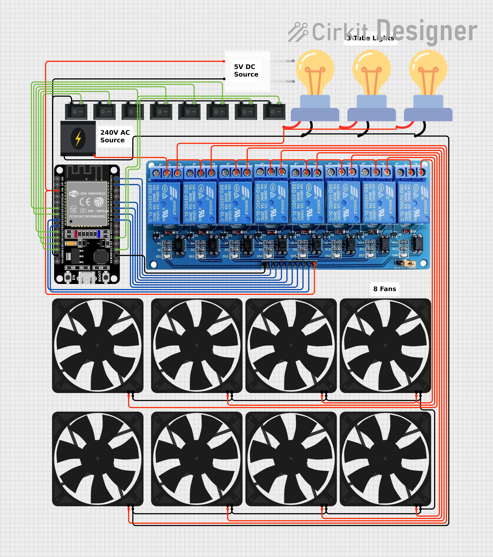
The circuit in question is designed to control multiple AC loads, including LED bulbs and fans, using an ESP32 microcontroller and a 5V 8-channel relay module. The ESP32 is programmed to interact with the relays, which in turn switch the connected loads. The circuit also includes manual control through rocker switches for each relay channel, providing both automated and manual control capabilities. The system is powered by a 240V power source, which is stepped down to 5V using an adapter to power the ESP32 and the relay module.
Component List
5V 8-Channel Relay
- Description: A relay module with 8 channels that can be controlled individually using input signals from the ESP32.
- Purpose: To switch AC loads on and off.
240V Power Source
- Description: A power source providing 240V AC.
- Purpose: To supply power to the AC loads and the 5V adapter.
ESP32 (30 pin)
- Description: A microcontroller with WiFi capabilities and multiple GPIO pins.
- Purpose: To control the relay module and provide connectivity for remote control.
5V Adapter
- Description: A power adapter that converts 240V AC to 5V DC.
- Purpose: To power the ESP32 and the relay module.
Rocker Switch (SPST)
- Description: A single-pole single-throw rocker switch.
- Purpose: To provide manual control over the relay channels.
LED bulb AC / Bombillo AC
- Description: An AC-powered LED bulb.
- Purpose: To act as a load controlled by the relay module.
Fan
- Description: A 5V DC fan.
- Purpose: To act as a load controlled by the relay module.
Wiring Details
5V 8-Channel Relay
- GND: Connected to the GND pin of the ESP32 and the GND of the 5V adapter.
- IN1-IN8: Connected to GPIO pins D23, D22, D21, D19, D18, D5, D25, and D26 of the ESP32 respectively.
- VCC: Connected to the 5V output of the 5V adapter.
- NC, C, NO: Normally Closed, Common, and Normally Open contacts used for relay channels.
240V Power Source
- Live: Connected to the Common (C) contacts of the relay module.
- Neutral: Connected to the Neutral lines of the LED bulbs and the GND of the fans.
ESP32 (30 pin)
- GND: Connected to the GND of the relay module and the GND of the 5V adapter.
- D23-D26, D5, D18-D22: Connected to the input pins IN1-IN8 of the relay module.
- D32, D33, D27, D14, D12, D13, D4, D15: Connected to the rocker switches for manual control.
5V Adapter
- AC In 1, AC In 2: Connected to the 240V power source.
- 5V: Connected to the VCC of the relay module and the Vin of the ESP32.
- GND: Connected to the GND of the relay module and the GND pin of the ESP32.
Rocker Switch (SPST)
- 1: Connected to the GND of the ESP32 and the GND of the 5V adapter.
- 2: Connected to GPIO pins D32, D33, D27, D14, D12, D13, D4, D15 of the ESP32 for manual control.
LED bulb AC / Bombillo AC
- + (Live): Connected to the Normally Open (NO) contacts of the relay module.
- - (Neutral): Connected to the Neutral line of the 240V power source.
Fan
- 5V: Connected to the Normally Open (NO) contacts of the relay module.
- GND: Connected to the Neutral line of the 240V power source.
Documented Code
/**********************************************************************************
 *  TITLE: ESP RainMaker + Manual Switch control 8 Relays using ESP32
 *  (Real time feedback + no WiFi control)
 *  by Tech StudyCell
 **********************************************************************************/

#include "RMaker.h"
#include "WiFi.h"
#include "WiFiProv.h"

// ... (initialization and setup code omitted for brevity)

void setup() {
    // Set the Relays GPIOs as output mode
    pinMode(RelayPin1, OUTPUT);
    pinMode(RelayPin2, OUTPUT);
    // ... (additional setup code omitted for brevity)

    // Configure the input GPIOs
    pinMode(SwitchPin1, INPUT_PULLUP);
    pinMode(SwitchPin2, INPUT_PULLUP);
    // ... (additional setup code omitted for brevity)

    // Write to the GPIOs the default state on booting
    digitalWrite(RelayPin1, !toggleState_1);
    digitalWrite(RelayPin2, !toggleState_2);
    // ... (additional setup code omitted for brevity)

    // ... (RainMaker initialization and setup code omitted for brevity)
}

void loop() {
    // ... (loop code omitted for brevity)

    manual_control(); // Function to handle manual switch control
}

// ... (additional functions and callbacks omitted for brevity)
The provided code snippet is part of a larger program that runs on the ESP32 microcontroller. It initializes the GPIO pins connected to the relay module and the manual switches, sets their default states, and includes a loop function that continuously checks for manual switch activations to control the relays. The full code includes additional setup for the ESP RainMaker platform, which allows for remote control and monitoring of the relays over WiFi.