
Circuit Documentation
Summary
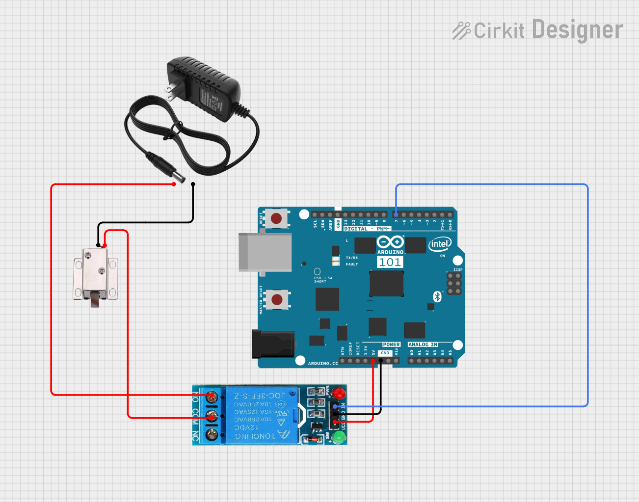
This circuit involves an Arduino 101 microcontroller, a 12V solenoid lock, a 12V single-channel relay, and a 12V power supply. The Arduino 101 controls the relay, which in turn controls the solenoid lock. The power supply provides the necessary voltage for the solenoid lock and the relay.
Component List
12V Solenoid Lock
- Description: A solenoid lock that operates at 12V.
- Pins: VCC, GND
Arduino 101
- Description: A microcontroller board based on the Intel Curie module.
- Pins: A5/SCL, A4/SDA, AREF, GND, D13/SCK, D12/MISO, D11 PWM/MOSI, D10 PWM/SS, D9 PWM, D8, D7, D6 PWM, D5 PWM, D4, D3 PWM, D2, D1/TX, D0/RX, AIN, ioref, RESET, 3V3, 5V, VIN, A0, A1, A2, A3, ICSP MISO, ICSP SCK, ICSP MOSI
12V Power Supply
- Description: A power supply that provides 12V DC.
- Pins: +, -
12V Single Channel Relay
- Description: A relay module that operates at 12V and can be controlled by a microcontroller.
- Pins: NC, COM, NO, IN, GND, VCC
Wiring Details
12V Solenoid Lock
- VCC is connected to COM of the 12V Single Channel Relay.
- GND is connected to - of the 12V Power Supply.
Arduino 101
- D7 is connected to IN of the 12V Single Channel Relay.
- 5V is connected to VCC of the 12V Single Channel Relay.
- GND is connected to GND of the 12V Single Channel Relay.
12V Power Supply
- + is connected to NO of the 12V Single Channel Relay.
- - is connected to GND of the 12V Solenoid Lock.
12V Single Channel Relay
- COM is connected to VCC of the 12V Solenoid Lock.
- IN is connected to D7 of the Arduino 101.
- VCC is connected to 5V of the Arduino 101.
- GND is connected to GND of the Arduino 101.
- NO is connected to + of the 12V Power Supply.
Code
There is no code provided for this circuit.