
Arduino UNO-Based Smart Temperature Control System with Wi-Fi and LCD Display
View and Edit Project In Cirkit Designer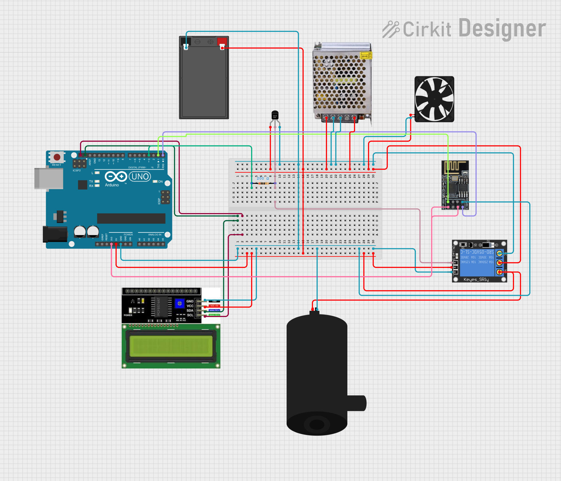
Circuit Documentation
Summary
This circuit is designed to monitor temperature and humidity using a DHT11 sensor and display the readings on an I2C LCD. It also includes a relay to control a water pump based on the temperature readings. The circuit is powered by a 12V power supply and includes an Arduino UNO as the main microcontroller, an ESP8266-01 WiFi module for connectivity, and additional components like a fan and a resistor.
Component List
Arduino UNO
- Description: Main microcontroller
- Pins: UNUSED, IOREF, Reset, 3.3V, 5V, GND, Vin, A0, A1, A2, A3, A4, A5, SCL, SDA, AREF, D13, D12, D11, D10, D9, D8, D7, D6, D5, D4, D3, D2, D1, D0
LCD I2C Display
- Description: 16x2 character display with I2C interface
- Pins: GND, VCC, SDA, SCL
1-Channel Relay (5V 10A)
- Description: Relay module for switching high-power devices
- Pins: NC, signal, C, power, NO, ground
POWER SUPPLY 12V 5AMP
- Description: Power supply unit
- Pins: 220V Positive Pole (AC), 220V Negative Pole (AC), GND, GND (DC), 12V-24V Output (DC)
DS18B20
- Description: Temperature sensor
- Pins: VDD, DQ, GND
Battery
- Description: Power source
- Pins: -, +
WiFi module ESP8266-01
- Description: WiFi module for connectivity
- Pins: RX, GPIO0, GPIO2, GND, +3V3, Reset, CH-PD Chip power down, TX
Water Pump
- Description: Pump for water circulation
- Pins: positive, negative
Resistor
- Description: 200 Ohms resistor
- Pins: pin1, pin2
Fan
- Description: Cooling fan
- Pins: GND, 5V
Wiring Details
Arduino UNO
- SDA connected to LCD I2C Display SDA
- SCL connected to LCD I2C Display SCL
- D3 connected to Resistor pin1
- GND connected to LCD I2C Display GND, Battery -, Water Pump negative, WiFi module ESP8266-01 GND, 1-Channel Relay ground, DS18B20 GND, POWER SUPPLY 12V 5AMP 220V Negative Pole (AC), POWER SUPPLY 12V 5AMP GND, Fan GND, 1-Channel Relay NC
- 5V connected to LCD I2C Display VCC, Battery +, 1-Channel Relay NO, Water Pump positive, 1-Channel Relay power, DS18B20 VDD, POWER SUPPLY 12V 5AMP 220V Positive Pole (AC), POWER SUPPLY 12V 5AMP 12V-24V Output (DC), Fan 5V, 1-Channel Relay C
- 3.3V connected to WiFi module ESP8266-01 +3V3, WiFi module ESP8266-01 CH-PD Chip power down
- D1 connected to WiFi module ESP8266-01 RX
- D0 connected to WiFi module ESP8266-01 TX
LCD I2C Display
- SDA connected to Arduino UNO SDA
- SCL connected to Arduino UNO SCL
- GND connected to Arduino UNO GND
- VCC connected to Arduino UNO 5V
1-Channel Relay (5V 10A)
- NC connected to Arduino UNO GND
- signal connected to Resistor pin2
- C connected to Arduino UNO 5V
- power connected to Arduino UNO 5V
- NO connected to Arduino UNO 5V
- ground connected to Arduino UNO GND
POWER SUPPLY 12V 5AMP
- 220V Positive Pole (AC) connected to Arduino UNO 5V
- 220V Negative Pole (AC) connected to Arduino UNO GND
- GND connected to Arduino UNO GND
- 12V-24V Output (DC) connected to Arduino UNO 5V
DS18B20
- VDD connected to Arduino UNO 5V
- DQ connected to Resistor pin2
- GND connected to Arduino UNO GND
Battery
- - connected to Arduino UNO GND
- + connected to Arduino UNO 5V
WiFi module ESP8266-01
- RX connected to Arduino UNO D1
- GND connected to Arduino UNO GND
- +3V3 connected to Arduino UNO 3.3V
- CH-PD Chip power down connected to Arduino UNO 3.3V
- TX connected to Arduino UNO D0
Water Pump
- positive connected to Arduino UNO 5V
- negative connected to Arduino UNO GND
Resistor
- pin1 connected to Arduino UNO D3
- pin2 connected to DS18B20 DQ, 1-Channel Relay signal
Fan
- GND connected to Arduino UNO GND
- 5V connected to Arduino UNO 5V
Documented Code
#include <DHT.h>
#include <Wire.h>
#include <LiquidCrystal_I2C.h>

// Define pin assignments
#define DHTPIN A3
#define DHTTYPE DHT11
#define UP_BUTTON_PIN 6
#define DOWN_BUTTON_PIN 7
#define RELAY_PIN 3

// Create DHT sensor object
DHT dht(DHTPIN, DHTTYPE);

// LCD setup (assuming you are using an I2C LCD)
LiquidCrystal_I2C lcd(0x27, 16, 2); // Adjust the address and size if necessary

// Variables
int setTemperature = 23; // Temperature to activate relay
const unsigned long INTERVAL = 1000; // Update interval for sensor readings
unsigned long previousTime = 0;

void setup() {
  Serial.begin(9600);

  pinMode(RELAY_PIN, OUTPUT);
  digitalWrite(RELAY_PIN, HIGH); // Initially turn off the relay

  pinMode(UP_BUTTON_PIN, INPUT_PULLUP);
  pinMode(DOWN_BUTTON_PIN, INPUT_PULLUP);

  dht.begin();

  lcd.init();
  lcd.backlight();
  lcd.setCursor(0, 0);
  lcd.print("Initializing...");
  delay(1000);

  lcd.clear();
  Serial.println("DHT11 Humidity & Temperature Sensor");
  delay(1000);
}

void loop() {
  unsigned long currentTime = millis();

  if (currentTime - previousTime >= INTERVAL) {
    previousTime = currentTime;

    // Read temperature and humidity
    float humidity = dht.readHumidity();
    float temperature = dht.readTemperature();

    // Check if readings failed
    if (isnan(humidity) || isnan(temperature)) {
      Serial.println("Failed to read from DHT sensor!");
      return;
    }

    // Print to Serial Monitor
    Serial.print("Current humidity = ");
    Serial.print(humidity, 1);
    Serial.print("%  Temperature = ");
    Serial.print(temperature, 1);
    Serial.print((char)223);
    Serial.println("C");

    // Display on LCD
    lcd.setCursor(0, 0);
    lcd.print("Hum:");
    lcd.print(humidity, 0);
    lcd.print("%");

    lcd.setCursor(0, 1);
    lcd.print("Temp:");
    lcd.print(temperature, 0);
    lcd.print((char)223);
    lcd.print("C");

    // Relay control
    if (temperature > setTemperature) {
      Serial.println("Relay: ON");
      lcd.setCursor(9, 0);
      lcd.print("SW:ON  ");
      digitalWrite(RELAY_PIN, LOW);
    } else {
      Serial.println("Relay: OFF");
      lcd.setCursor(9, 0);
      lcd.print("SW:OFF ");
      digitalWrite(RELAY_PIN, HIGH);
    }

    // Button handling
    if (digitalRead(UP_BUTTON_PIN) == LOW) {
      setTemperature++;
      delay(200); // Debounce delay
    }

    if (digitalRead