
Arduino Nano-Based RGB LED Matrix with Pushbutton Control and Battery Power
View and Edit Project In Cirkit Designer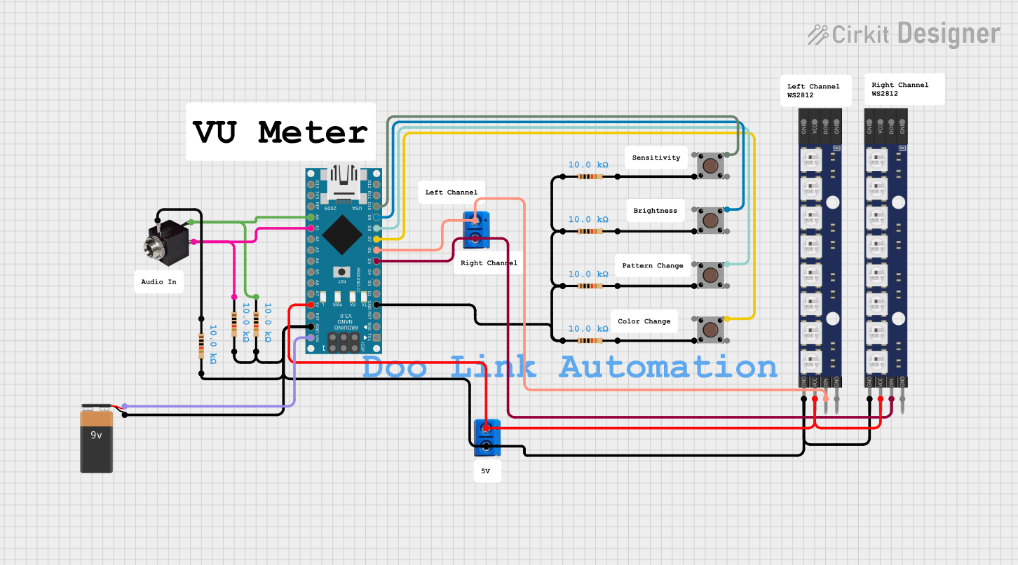
Circuit Documentation
Summary
This circuit involves an Arduino Nano microcontroller, several resistors, pushbuttons, WS2812 RGB LED matrices, a 9V battery, and terminal PCB connectors. The circuit is designed to control the LED matrices and read inputs from the pushbuttons.
Component List
Arduino Nano
- Description: A small, complete, and breadboard-friendly board based on the ATmega328P.
- Pins: D1/TX, D0/RX, RESET, GND, D2, D3, D4, D5, D6, D7, D8, D9, D10, D11/MOSI, D12/MISO, VIN, 5V, A7, A6, A5, A4, A3, A2, A1, A0, AREF, 3V3, D13/SCK
Resistor
- Description: A passive electrical component that implements electrical resistance as a circuit element.
- Pins: pin1, pin2
- Properties:
- Resistance: 10000 Ohms
Terminal PCB 2 Pin
- Description: A connector with two pins for connecting wires to a PCB.
- Pins: Pin A, Pin B
WS2812 RGB LED Matrix 1x8
- Description: An 8-LED RGB matrix with individually addressable LEDs.
- Pins: VCC, GND, DOUT, DIN
3.5mm Jack Base
- Description: A base for a 3.5mm audio jack.
- Pins: None specified
Pushbutton
- Description: A simple pushbutton switch.
- Pins: Pin 3 (out), Pin 4 (out), Pin 1 (in), Pin 2 (in)
9V Battery
- Description: A standard 9V battery.
- Pins: None specified
Comment
- Description: Placeholder for comments in the circuit.
- Pins: None specified
Wiring Details
Arduino Nano
- GND: Connected to pin1 of multiple resistors.
- D5: Connected to Pin B of a Terminal PCB 2 Pin and DIN of a WS2812 RGB LED matrix.
- D6: Connected to Pin A of a Terminal PCB 2 Pin and DIN of another WS2812 RGB LED matrix.
- D7: Connected to Pin 1 (in) of a pushbutton.
- D8: Connected to Pin 1 (in) of another pushbutton.
- D9: Connected to Pin 1 (in) of another pushbutton.
- D10: Connected to Pin 1 (in) of another pushbutton.
- VIN: Connected to the 9V battery.
- 5V: Connected to VCC of two WS2812 RGB LED matrices and Pin A of a Terminal PCB 2 Pin.
- A1: Connected to pin1 of a resistor and a 3.5mm jack base.
- A0: Connected to pin1 of another resistor and a 3.5mm jack base.
Resistor
- pin1: Connected to GND of the Arduino Nano and other resistors.
- pin2: Connected to GND of the Arduino Nano, GND of WS2812 RGB LED matrices, and other resistors.
- pin2: Connected to Pin 4 (out) of pushbuttons.
Terminal PCB 2 Pin
- Pin A: Connected to D6 of the Arduino Nano and DIN of a WS2812 RGB LED matrix.
- Pin B: Connected to D5 of the Arduino Nano and DIN of another WS2812 RGB LED matrix.
WS2812 RGB LED Matrix 1x8
- VCC: Connected to 5V of the Arduino Nano.
- GND: Connected to GND of the Arduino Nano and other components.
- DIN: Connected to D5 and D6 of the Arduino Nano through Terminal PCB 2 Pins.
Pushbutton
- Pin 1 (in): Connected to D7, D8, D9, and D10 of the Arduino Nano.
- Pin 4 (out): Connected to pin2 of resistors.
9V Battery
- Connected to: VIN and GND of the Arduino Nano.
Code Documentation
Arduino Nano Code
void setup() {
  // put your setup code here, to run once:

}

void loop() {
  // put your main code here, to run repeatedly:

}
This code is a basic template for the Arduino Nano. The setup() function is where you initialize your variables, pin modes, start using libraries, etc. The loop() function is where you write the main code that you want to run repeatedly.
This documentation provides a comprehensive overview of the circuit, including a detailed list of components, their connections, and the code used in the microcontroller.