
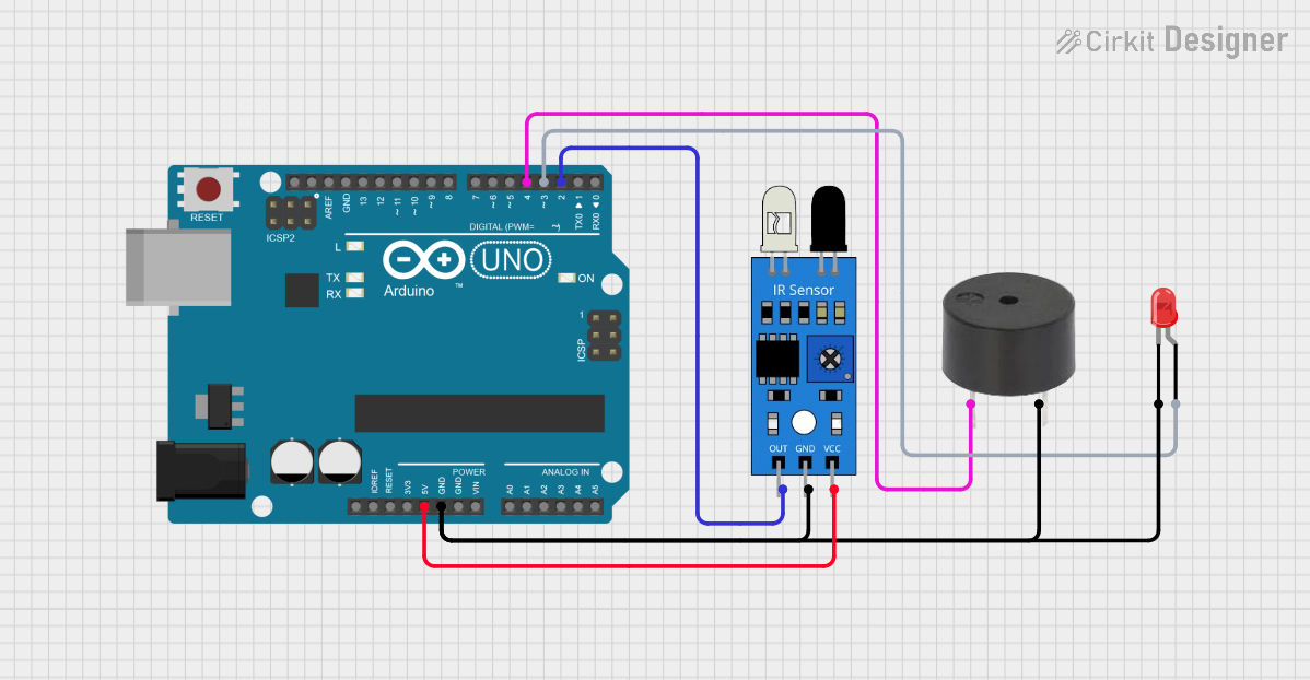
Circuit Documentation
Summary
The circuit consists of an Arduino UNO microcontroller interfaced with an IR sensor, a buzzer, and a red two-pin LED. The IR sensor is used to detect the presence of an object, and upon detection, the Arduino activates the buzzer and the LED to signal that an object has been detected. The circuit is powered by the 5V output from the Arduino, and a common ground is shared among all components.
Component List
Arduino UNO
- Description: A microcontroller board based on the ATmega328P.
- Pins Used:
5V- Provides power to the IR sensor.GND- Common ground for the circuit.D2- Receives the output signal from the IR sensor.D3- Controls the anode of the LED.D4- Controls the buzzer.
IR Sensor
- Description: A sensor that detects the presence of an object by using infrared light.
- Pins Used:
out- Sends the detection signal to the Arduino.gnd- Connected to the common ground.vcc- Powered by the 5V supply from the Arduino.
Buzzer
- Description: An electronic buzzer that emits sound when powered.
- Pins Used:
PIN- Controlled by the Arduino to emit sound.GND- Connected to the common ground.
LED: Two Pin (red)
- Description: A red LED that lights up when powered.
- Pins Used:
anode- Controlled by the Arduino to turn the LED on and off.cathode- Connected to the common ground.
Wiring Details
Arduino UNO
5Vconnected to IR sensorvcc.GNDconnected to IR sensorgnd, LEDcathode, and buzzerGND.D2connected to IR sensorout.D3connected to LEDanode.D4connected to buzzerPIN.
IR Sensor
vccconnected to Arduino UNO5V.gndconnected to Arduino UNOGND.outconnected to Arduino UNOD2.
Buzzer
PINconnected to Arduino UNOD4.GNDconnected to Arduino UNOGND.
LED: Two Pin (red)
anodeconnected to Arduino UNOD3.cathodeconnected to Arduino UNOGND.
Documented Code
// Code for Arduino UNO
int sensorPin = 2;    // IR sensor pin
int ledPin = 3;       // LED pin
int buzzerPin = 4;    // Buzzer pin

void setup() {
  pinMode(sensorPin, INPUT);    // Set IR sensor pin as input
  pinMode(ledPin, OUTPUT);      // Set LED pin as output
  pinMode(buzzerPin, OUTPUT);   // Set buzzer pin as output
}

void loop() {
  int objectDetected = digitalRead(sensorPin);  // Read the sensor value

  if (objectDetected == LOW) {  // Assuming LOW means object detected
    digitalWrite(ledPin, HIGH);  // Turn LED on
    digitalWrite(buzzerPin, HIGH);  // Turn Buzzer on
  } else {
    digitalWrite(ledPin, LOW);   // Turn LED off
    digitalWrite(buzzerPin, LOW);  // Turn Buzzer off
  }
}
The code is written for the Arduino UNO and is responsible for reading the output of the IR sensor. When the sensor detects an object (signaled by a LOW reading), the Arduino turns on the LED and the buzzer. When no object is detected, the LED and the buzzer are turned off. The setup() function initializes the pins, and the loop() function contains the main logic that is executed repeatedly.