
Circuit Documentation
Summary
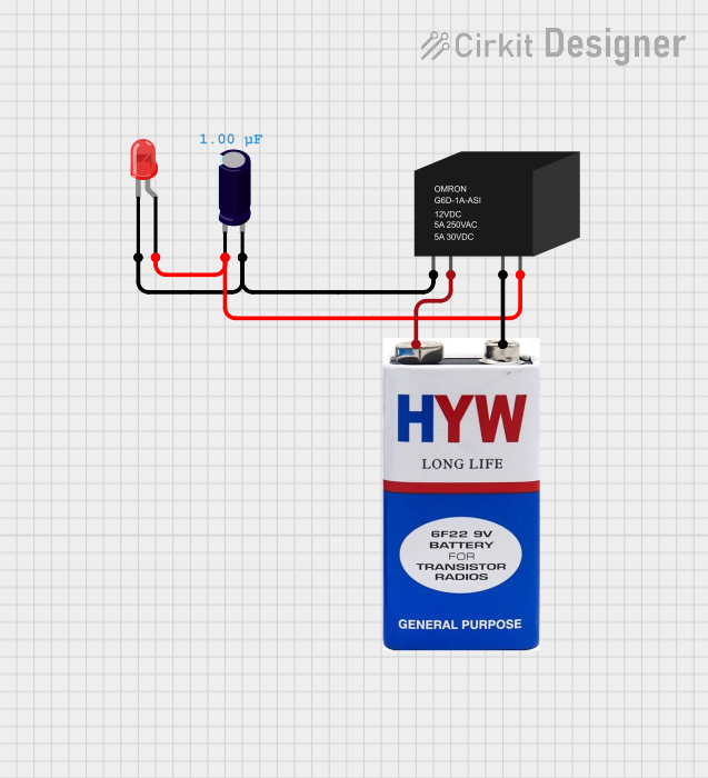
This document provides a detailed description of a circuit that includes a relay, an electrolytic capacitor, an LED, and a 9V battery. The circuit is designed to control the LED using the relay, with the capacitor providing additional functionality.
Component List
RELAY-G5D
- Pins: COIL1, COIL2, NO, COM
- Description: A relay used to control the LED.
- Purpose: To switch the LED on and off.
Electrolytic Capacitor
- Pins: -, +
- Description: A capacitor used for energy storage.
- Purpose: To provide additional functionality in the circuit.
- Properties:
- Capacitance: 1 µF
LED: Two Pin (red)
- Pins: cathode, anode
- Description: A red LED.
- Purpose: To indicate the status of the relay.
9V battery
- Pins: +, -
- Description: A 9V battery.
- Purpose: To provide power to the circuit.
Wiring Details
RELAY-G5D
COIL1 is connected to:
- cathode of the LED
- + of the Electrolytic Capacitor
COIL2 is connected to:
- + of the 9V battery
NO is connected to:
- - of the 9V battery
COM is connected to:
- anode of the LED
- - of the Electrolytic Capacitor
Electrolytic Capacitor
+ is connected to:
- COIL1 of the RELAY-G5D
- cathode of the LED
- is connected to:
- COM of the RELAY-G5D
- anode of the LED
LED: Two Pin (red)
cathode is connected to:
- COIL1 of the RELAY-G5D
- + of the Electrolytic Capacitor
anode is connected to:
- COM of the RELAY-G5D
- - of the Electrolytic Capacitor
9V battery
+ is connected to:
- COIL2 of the RELAY-G5D
- is connected to:
- NO of the RELAY-G5D
Code
There is no microcontroller code associated with this circuit.