
Arduino Mega 2560 Controlled LED Indicators and Servo with Buzzer Notification System
View and Edit Project In Cirkit Designer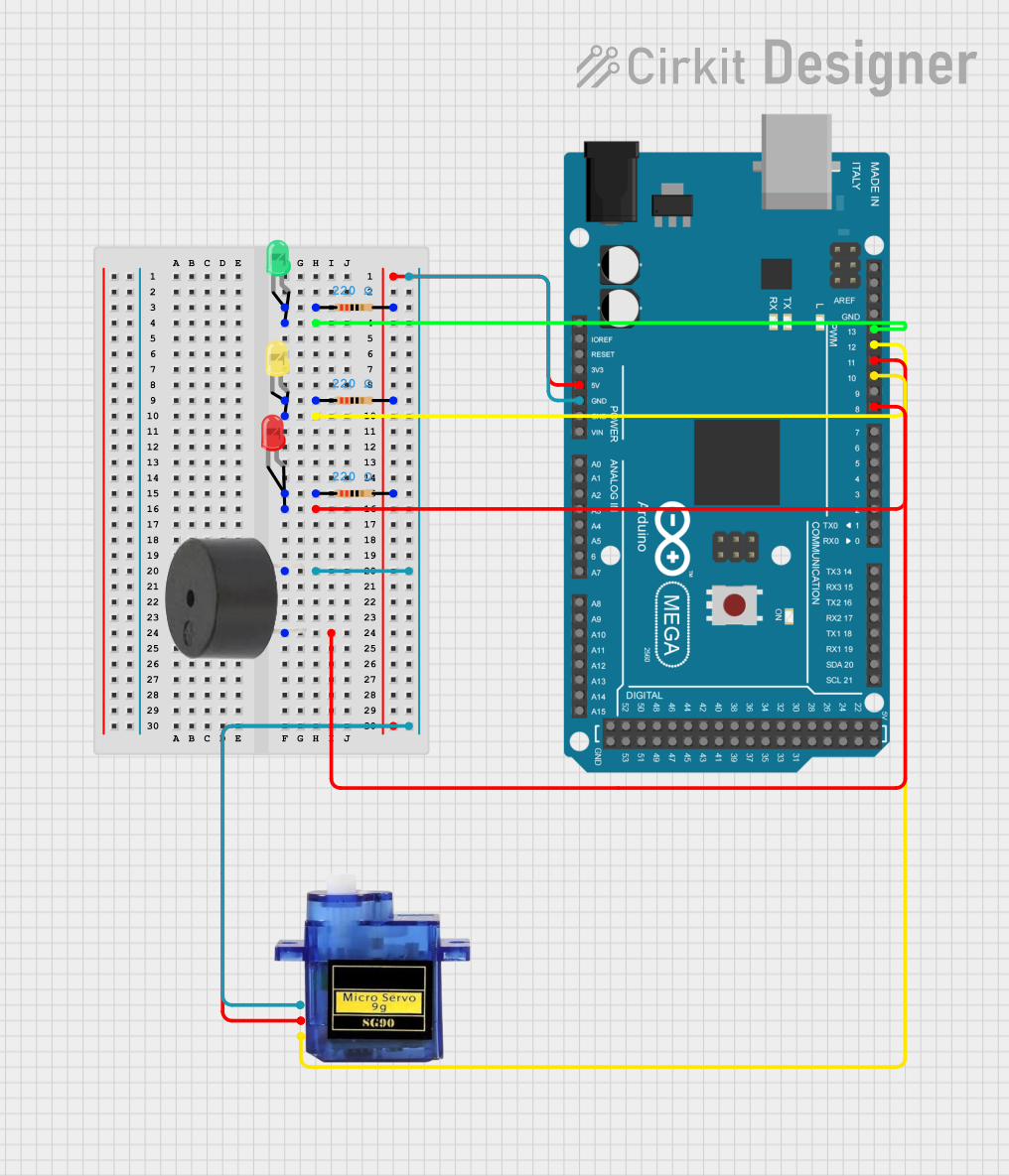
Circuit Documentation
Summary
The circuit is designed around the Arduino Mega 2560 microcontroller, which controls various peripherals including LEDs, a buzzer, and a micro servo. The LEDs are connected to the digital pins with PWM capability for potential brightness control, and each LED is paired with a resistor to limit the current. The micro servo is powered by the 5V supply from the Arduino and controlled via a PWM signal. The buzzer is also connected to a PWM pin for sound generation. The ground connections are shared among the components, establishing a common reference point for the circuit.
Component List
Arduino Mega 2560
- Microcontroller board based on the ATmega2560
- It has 54 digital input/output pins (of which 15 can be used as PWM outputs), 16 analog inputs, 4 UARTs (hardware serial ports), a 16 MHz crystal oscillator, a USB connection, a power jack, an ICSP header, and a reset button.
LED: Two Pin (green)
- A green light-emitting diode (LED) for visual signaling
- Requires current-limiting resistor to prevent damage
LED: Two Pin (red)
- A red light-emitting diode (LED) for visual signaling
- Requires current-limiting resistor to prevent damage
LED: Two Pin (yellow)
- A yellow light-emitting diode (LED) for visual signaling
- Requires current-limiting resistor to prevent damage
Resistor (220 Ohms)
- Three resistors with a resistance of 220 Ohms each
- Used to limit the current through the LEDs
Micro servo 9G
- A small servo motor capable of precise position control
- Operates on +5V and receives control signals via PWM
Buzzer
- An electronic buzzer for audible signaling
- Can be driven by a PWM signal to generate different tones
Wiring Details
Arduino Mega 2560
- 5V: Connected to the +5V pins of the micro servo and the anode side of the resistors for the LEDs
- GND: Connected to the GND pins of the buzzer and micro servo, and the cathode side of the LEDs
- D13 PWM: Connected to the anode of the green LED (through a resistor)
- D12 PWM: Connected to the anode of the yellow LED (through a resistor)
- D11 PWM: Connected to the anode of the red LED (through a resistor)
- D10 PWM: Connected to the PWM pin of the micro servo
- D8 PWM: Connected to the PIN pin of the buzzer
LED: Two Pin (green)
- Anode: Connected to D13 PWM on the Arduino Mega 2560 (through a 220 Ohm resistor)
- Cathode: Connected to GND
LED: Two Pin (red)
- Anode: Connected to D11 PWM on the Arduino Mega 2560 (through a 220 Ohm resistor)
- Cathode: Connected to GND
LED: Two Pin (yellow)
- Anode: Connected to D12 PWM on the Arduino Mega 2560 (through a 220 Ohm resistor)
- Cathode: Connected to GND
Resistor (220 Ohms)
- One side (pin1): Connected to the cathode of the corresponding LED
- Other side (pin2): Connected to the 5V supply from the Arduino Mega 2560
Micro servo 9G
- +5V: Connected to the 5V output from the Arduino Mega 2560
- GND: Connected to GND on the Arduino Mega 2560
- PWM: Connected to D10 PWM on the Arduino Mega 2560
Buzzer
- PIN: Connected to D8 PWM on the Arduino Mega 2560
- GND: Connected to GND on the Arduino Mega 2560
Documented Code
Arduino Mega 2560 - sketch.ino
void setup() {
  // put your setup code here, to run once:

}

void loop() {
  // put your main code here, to run repeatedly:

}
Arduino Mega 2560 - documentation.txt
(No additional documentation provided for the code)