Cirkit Designer
Your all-in-one circuit design IDE
Home /
Project Documentation
Arduino UNO Ultrasonic Distance Sensor with LED and Buzzer Alert System
Circuit Documentation
Summary
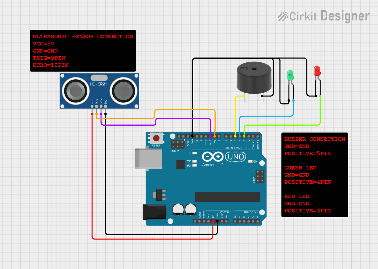
This circuit involves an Arduino UNO microcontroller interfacing with an HC-SR04 Ultrasonic Sensor, a buzzer, and two LEDs (one red and one green). The Arduino UNO is used to control the LEDs and the buzzer based on the input from the ultrasonic sensor.
Component List
Arduino UNO
- Description: A microcontroller board based on the ATmega328P.
- Pins: UNUSED, IOREF, Reset, 3.3V, 5V, GND, Vin, A0, A1, A2, A3, A4, A5, SCL, SDA, AREF, D13, D12, D11, D10, D9, D8, D7, D6, D5, D4, D3, D2, D1, D0
LED: Two Pin (red)
- Description: A red LED with two pins: cathode and anode.
- Pins: cathode, anode
LED: Two Pin (green)
- Description: A green LED with two pins: cathode and anode.
- Pins: cathode, anode
Buzzer
- Description: A simple buzzer with two pins: PIN and GND.
- Pins: PIN, GND
HC-SR04 Ultrasonic Sensor
- Description: An ultrasonic sensor used for distance measurement.
- Pins: VCC, TRIG, ECHO, GND
Wiring Details
Arduino UNO
- 5V: Connected to VCC of the HC-SR04 Ultrasonic Sensor.
- GND: Connected to GND of the HC-SR04 Ultrasonic Sensor, cathode of the red LED, cathode of the green LED, and GND of the buzzer.
- D10: Connected to ECHO of the HC-SR04 Ultrasonic Sensor.
- D9: Connected to TRIG of the HC-SR04 Ultrasonic Sensor.
- D5: Connected to PIN of the buzzer.
- D4: Connected to anode of the green LED.
- D3: Connected to anode of the red LED.
LED: Two Pin (red)
- cathode: Connected to GND of the Arduino UNO.
- anode: Connected to D3 of the Arduino UNO.
LED: Two Pin (green)
- cathode: Connected to GND of the Arduino UNO.
- anode: Connected to D4 of the Arduino UNO.
Buzzer
- PIN: Connected to D5 of the Arduino UNO.
- GND: Connected to GND of the Arduino UNO.
HC-SR04 Ultrasonic Sensor
- VCC: Connected to 5V of the Arduino UNO.
- TRIG: Connected to D9 of the Arduino UNO.
- ECHO: Connected to D10 of the Arduino UNO.
- GND: Connected to GND of the Arduino UNO.
Code Documentation
sketch.ino
void setup() {
  // put your setup code here, to run once:

}

void loop() {
  // put your main code here, to run repeatedly:

}
documentation.txt