
Circuit Documentation
Summary of the Circuit
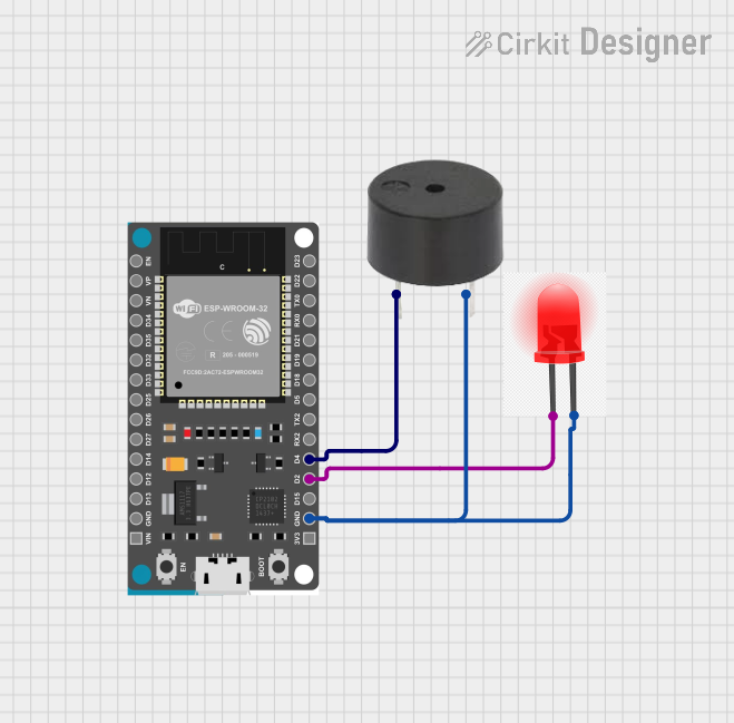
This circuit consists of an ESP32 Devkit V1 microcontroller, a buzzer, and a red LED. The ESP32 Devkit V1 is the central processing unit of the circuit, capable of controlling the buzzer and the LED. The buzzer can provide audible feedback, while the LED serves as a visual indicator. The ground (GND) connections are shared among all components, creating a common reference point for the circuit's power supply.
Component List
ESP32 Devkit V1
- Description: A microcontroller development board based on the ESP32 chip, suitable for a variety of IoT applications.
- Pins: 3V3, GND, D15, D2, D4, RX2, TX2, D5, D18, D19, D21, RX0, TX0, D22, D23, EN, VP, VN, D34, D35, D32, D33, D25, D26, D27, D14, D12, D13, VIN
Buzzer
- Description: An electromechanical component that emits sound when an electrical signal is applied.
- Pins: PIN, GND
LED RED
- Description: A red light-emitting diode used as an indicator light.
- Pins: +, -
Wiring Details
ESP32 Devkit V1
- GND: Connected to the ground pins of the buzzer and the red LED.
- D2: Connected to the positive pin (+) of the red LED.
- D4: Connected to the PIN of the buzzer.
Buzzer
- PIN: Connected to pin D4 of the ESP32 Devkit V1.
- GND: Shared ground connection with the ESP32 Devkit V1 and the red LED.
LED RED
- +: Connected to pin D2 of the ESP32 Devkit V1.
- _: Shared ground connection with the ESP32 Devkit V1 and the buzzer.
Documented Code
There is no code provided for the microcontrollers in the circuit. If code is later provided, it should be documented here with explanations of how the microcontroller interfaces with the buzzer and the LED, including any initialization code, control logic, and relevant functions or routines.