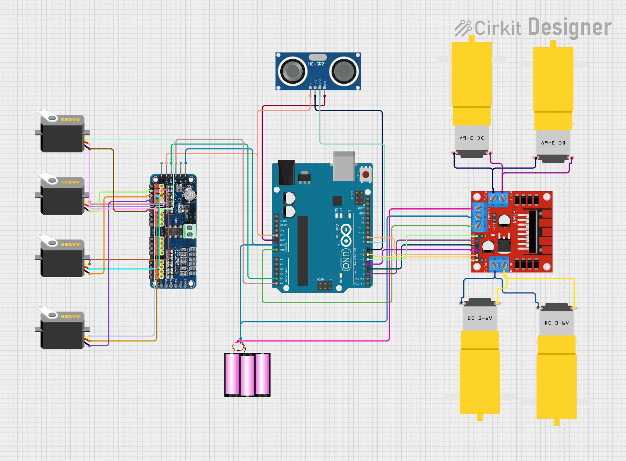
Arduino-Controlled Robotics Platform with Ultrasonic Sensing and Servo Motor Integration

Circuit Documentation
Summary
This circuit is designed to interface an Arduino UNO with a variety of components including an HC-SR04 Ultrasonic Sensor, an L298N DC motor driver, four hobbyist yellow geared motors, a 16-Channel PWM Servo Driver, four servos, and a 12V battery. The Arduino UNO serves as the central processing unit, controlling the motors and reading sensor data. The L298N driver is used to control the motors, while the 16-Channel PWM Servo Driver manages the servos. The HC-SR04 sensor provides distance measurements. Power distribution is carefully managed to ensure all components receive the appropriate voltages.
Component List
- Arduino UNO: A microcontroller board based on the ATmega328P, featuring digital and analog I/O pins.
- HC-SR04 Ultrasonic Sensor: A sensor for measuring distance via ultrasonic sound waves.
- L298N DC Motor Driver: A module for controlling up to two DC motors with direction and speed control.
- Motor Amarillo Motorreductor Hobby: Four yellow hobbyist geared motors for mechanical movement.
- 16-Channel PWM Servo Driver: A board capable of controlling up to 16 servos with Pulse Width Modulation.
- Servo: Four servos for precise angular movement.
- Battery 12V: A 12V battery to power the motor driver and potentially other components.
Wiring Details
Arduino UNO
5Vconnected to HC-SR04 VCC and 16-Channel PWM Servo Driver VCC.GNDconnected to HC-SR04 GND, L298N GND, and 16-Channel PWM Servo Driver GND.Vinconnected to L298N 5V.A4 (SDA)connected to 16-Channel PWM Servo Driver SDA.A5 (SCL)connected to 16-Channel PWM Servo Driver SCL.D2-D9connected to L298N IN1-IN4, ENA, ENB, HC-SR04 TRIG, and ECHO.
HC-SR04 Ultrasonic Sensor
VCCconnected to Arduino UNO 5V.GNDconnected to Arduino UNO GND.TRIGconnected to Arduino UNO D7.ECHOconnected to Arduino UNO D8.
L298N DC Motor Driver
12Vconnected to Battery 12V (+).GNDconnected to Battery 12V (-) and Arduino UNO GND.5Vconnected to Arduino UNO Vin.IN1-IN4connected to Arduino UNO D2-D4, D9.ENA, ENBconnected to Arduino UNO D5, D6.OUT1-OUT4connected to the respective pairs of Motor Amarillo Motorreductor Hobby vcc and GND.
Motor Amarillo Motorreductor Hobby
- Four motors with
vccandGNDconnected to L298N OUT1-OUT4.
16-Channel PWM Servo Driver
VCCconnected to Arduino UNO 5V.GNDconnected to Arduino UNO GND and all Servo gnd.SDAconnected to Arduino UNO A4.SCLconnected to Arduino UNO A5.V+connected to all Servo vcc.PWM1-PWM16connected to respective Servo pulse pins.
Servo
- Four servos with
vccconnected to 16-Channel PWM Servo Driver V+. gndconnected to 16-Channel PWM Servo Driver GND.pulseconnected to 16-Channel PWM Servo Driver PWM2-PWM5.
Battery 12V
+connected to L298N 12V.-connected to L298N GND.
Documented Code
Arduino UNO Code (sketch.ino)
void setup() {
  // put your setup code here, to run once:

}

void loop() {
  // put your main code here, to run repeatedly:

}
This code is a template for the Arduino UNO and does not contain any functional code. It provides the basic structure for an Arduino sketch with setup() and loop() functions. The setup() function is intended for initialization code that runs once, while the loop() function contains code that runs repeatedly.
Additional Notes
The provided code is a placeholder and needs to be populated with the logic to control the motors via the L298N driver, read distance measurements from the HC-SR04 sensor, and manage the servos using the 16-Channel PWM Servo Driver. The actual implementation will depend on the specific requirements of the application this circuit is intended for.