Cirkit Designer
Your all-in-one circuit design IDE
Home /
Project Documentation
RFID Attendance System with SMS Alerts and RTC Synchronization

RFID Attendance System Documentation
Summary
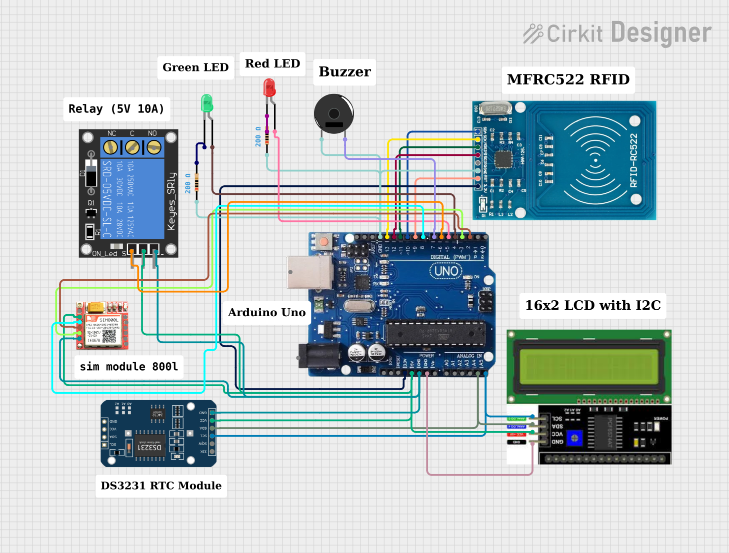
The RFID Attendance System is designed to log attendance using an RFID reader, monitor the time with an RTC module, send messages via a SIM800L module, provide alerts with a buzzer, and display messages on an LCD. It also uses two LEDs to indicate access status. The system is controlled by an Arduino Uno R3 microcontroller.
Component List
RFID-RC522
- Description: RFID reader module for reading RFID tags.
- Pins: VCC (3.3V), RST, GND, IRQ, MISO, MOSI, SCK, SDA.
Piezo Buzzer
- Description: A buzzer for audible alerts.
- Pins: pin 1, pin 2.
LCD I2C Display
- Description: An LCD display with I2C interface for displaying messages.
- Pins: GND, VCC, SDA, SCL.
Resistor (200 Ohms)
- Description: A resistor with a resistance of 200 Ohms.
- Pins: pin1, pin2.
LED: Two Pin (red)
- Description: A red LED for status indication.
- Pins: cathode, anode.
LED: Two Pin (green)
- Description: A green LED for status indication.
- Pins: cathode, anode.
DS3231 RTC
- Description: Real-Time Clock module for timekeeping.
- Pins: 32K, SQW, SCL, SDA, VCC, GND.
SIM800L
- Description: GSM/GPRS module for sending SMS messages.
- Pins: NFT, RING, VCC, DTR, RST, MIC +, RXD, MIC-, TXD, SPK+, GND, SPK-.
1-Channel Relay (5V 10A)
- Description: A relay module for controlling high power devices.
- Pins: NC, signal, C, power, NO, ground.
Arduino Uno R3
- Description: Microcontroller board based on the ATmega328P.
- Pins: USB Port, Power Jack, Not Connected, IOREF, RESET, 3.3V, 5V, GND, VIN, A0-A5, SCL, SDA, AREF, digital pins 0-13.
Wiring Details
RFID-RC522
- VCC (3.3V) connected to Arduino Uno R3 3.3V.
- RST connected to Arduino Uno R3 pin 9.
- GND connected to Arduino Uno R3 GND.
- MISO connected to Arduino Uno R3 pin 12.
- MOSI connected to Arduino Uno R3 pin 11.
- SCK connected to Arduino Uno R3 pin 13.
- SDA connected to Arduino Uno R3 pin 10.
Piezo Buzzer
- pin 1 connected to Arduino Uno R3 GND through a 200 Ohm resistor.
- pin 2 connected to Arduino Uno R3 pin 7.
LCD I2C Display
- GND connected to Arduino Uno R3 GND.
- VCC connected to Arduino Uno R3 5V.
- SDA connected to Arduino Uno R3 A4/SDA.
- SCL connected to Arduino Uno R3 A5/SCL.
Resistor (200 Ohms)
- One resistor connected between Arduino Uno R3 GND and Piezo Buzzer pin 1.
- Another resistor connected between Arduino Uno R3 GND and the cathode of the red LED.
LED: Two Pin (red)
- Anode connected to Arduino Uno R3 pin 5.
- Cathode connected to GND through a 200 Ohm resistor.
LED: Two Pin (green)
- Anode connected to Arduino Uno R3 pin 4.
- Cathode connected to GND through a 200 Ohm resistor.
DS3231 RTC
- SCL connected to Arduino Uno R3 A5/SCL.
- SDA connected to Arduino Uno R3 A4/SDA.
- VCC connected to Arduino Uno R3 5V.
- GND connected to Arduino Uno R3 GND.
SIM800L
- RST connected to Arduino Uno R3 pin 8.
- TXD connected to Arduino Uno R3 pin 3.
- RXD connected to Arduino Uno R3 pin 2.
- VCC connected to Arduino Uno R3 5V.
- GND connected to Arduino Uno R3 GND.
1-Channel Relay (5V 10A)
- signal connected to Arduino Uno R3 pin 6.
- power connected to Arduino Uno R3 5V.
- ground connected to Arduino Uno R3 GND.
Documented Code
/*
 * RFID Attendance System using Arduino Uno R3
 * This system uses an RFID reader to log attendance, an RTC to check the time,
 * a SIM800L module to send messages to parents, a buzzer for alerts, an LCD
 * display for messages, and two LEDs to indicate access status.
 */

#include <Wire.h>
#include <LiquidCrystal_I2C.h>
#include <SPI.h>
#include <MFRC522.h>
#include <DS3231.h>
#include <SoftwareSerial.h>

// Pin definitions
#define RST_PIN 9
#define SS_PIN 10
#define GREEN_LED_PIN 4
#define RED_LED_PIN 5
#define BUZZER_PIN 7
#define RELAY_PIN 6
#define SIM800_TX 3
#define SIM800_RX 2

// Initialize components
LiquidCrystal_I2C lcd(0x27, 16, 2);
MFRC522 rfid(SS_PIN, RST_PIN);
DS3231 rtc(SDA, SCL);
SoftwareSerial sim800(SIM800_TX, SIM800_RX);

void setup() {
  // Initialize serial communication
  Serial.begin(9600);
  sim800.begin(9600);

  // Initialize LCD
  lcd.begin();
  lcd.backlight();

  // Initialize RFID
  SPI.begin();
  rfid.PCD_Init();

  // Initialize RTC
  rtc.begin();

  // Initialize pins
  pinMode(GREEN_LED_PIN, OUTPUT);
  pinMode(RED_LED_PIN, OUTPUT);
  pinMode(BUZZER_PIN, OUTPUT);
  pinMode(RELAY_PIN, OUTPUT);

  // Welcome message
  lcd.setCursor(0, 0);
  lcd.print("RFID Attendance");
  lcd.setCursor(0, 1);
  lcd.print("System");
  delay(2000);
  lcd.clear();
}

void loop() {
  // Check for RFID card
  if (!rfid.PICC_IsNewCardPresent() || !rfid.PICC_ReadCardSerial()) {
    return;
  }

  // Get current time
  DateTime now = rtc.now();

  // Check if student is on time
  if (isOnTime(now)) {
    grantAccess();
  } else {
    denyAccess();
  }

  // Halt PICC
  rfid.PICC_HaltA();
}

bool isOnTime(DateTime now) {
  // Define the allowed time range (e.g., 8:00 AM to 9:00 AM)
  DateTime start(2023, 1, 1, 8, 0, 0);
  DateTime end(2023, 1, 1, 9, 0, 0);
  return now >= start && now <= end;
}

void grantAccess() {
  // Turn on green LED
  digitalWrite(GREEN_LED_PIN, HIGH);
  digitalWrite(RED_LED_PIN, LOW);

  // Activate relay
  digitalWrite(RELAY_PIN, HIGH);

  // Display message
  lcd.setCursor(0, 0);
  lcd.print("Access Granted");

  // Send SMS
  sendSMS("Access Granted");

  // Deactivate relay after delay
  delay(5000);
  digitalWrite(RELAY_PIN, LOW);
  lcd.clear();
}

void denyAccess() {
  // Turn on red LED
  digitalWrite(RED_LED_PIN, HIGH);
  digitalWrite(GREEN_LED_PIN, LOW);

  // Activate buzzer
  digitalWrite(BUZZER_PIN, HIGH);
  delay(1000);
  digitalWrite(BUZZER_PIN, LOW);

  // Display message
  lcd.setCursor(0, 0);
  lcd.print("Access Denied");

  // Send SMS
  sendSMS("Access Denied");

  delay(5000);
  lcd.clear();
}

void sendSMS(String message) {
  sim800.print("AT+CMGF=1\r");
  delay(100);
  sim800.print("AT+CMGS=\"+1234567890\"\r");
  delay(100);
  sim800.print(message);
  delay(100);
  sim800.write(26);
  delay(1000);
}
This code is responsible for controlling the RFID Attendance System. It initializes the components, checks for RFID cards, determines if the scanned card is within the allowed time range, and grants or denies access accordingly. It also sends SMS messages and controls the LEDs and buzzer for visual and audible feedback.