
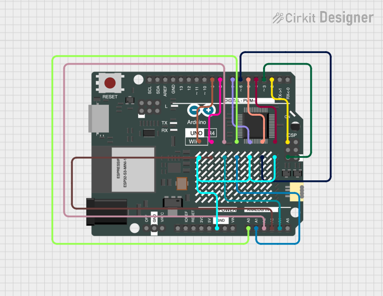
Circuit Documentation
Summary
This circuit consists of an LED Matrix 64x32 display panel controlled by an Arduino UNO R4 WiFi microcontroller. The Arduino is programmed to iterate through a range of colors, displaying them on the LED matrix. The matrix is connected to the Arduino through various digital and analog pins, allowing for the control of individual LEDs and the synchronization of the display.
Component List
LED Matrix 64x32
- Description: A 64x32 pixel LED display matrix capable of displaying multiple colors.
- Pins: R1, B1, R2, B2, A, C, CLK, OE, G1, GND, G2, B, D, LAT
Arduino UNO R4 WiFi
- Description: A microcontroller board based on the ATmega328, with integrated WiFi capabilities.
- Pins: OFF, GND, VRTC, IIC0_SCL, IIC0_SDA, 3V3, GPIO 41, GPIO 0, GPIO 42, GPIO 43, GPIO 44, BOOT, IOREF, RESET, 5V, VIN, A0, A1, A2, A3, A4, A5, RSPCKA, CIPO, COPI, D0/RX, D1/TX, D2, D3, D4, D5, D6, D7, D8, D9, D10, D11, D12, D13, AREF, SDA, SCL
Wiring Details
LED Matrix 64x32
- R1 connected to Arduino D2
- B1 connected to Arduino D4
- R2 connected to Arduino D5
- B2 connected to Arduino D7
- A connected to Arduino A0
- C connected to Arduino A2
- CLK connected to Arduino D8
- OE connected to Arduino D9
- G1 connected to Arduino D3
- GND connected to Arduino GND
- G2 connected to Arduino D6
- B connected to Arduino A1
- D connected to Arduino A4
- LAT connected to Arduino A3
Arduino UNO R4 WiFi
- D2 connected to LED Matrix R1
- D4 connected to LED Matrix B1
- D5 connected to LED Matrix R2
- D7 connected to LED Matrix B2
- A0 connected to LED Matrix A
- A2 connected to LED Matrix C
- D8 connected to LED Matrix CLK
- D9 connected to LED Matrix OE
- D3 connected to LED Matrix G1
- GND connected to LED Matrix GND
- D6 connected to LED Matrix G2
- A1 connected to LED Matrix B
- A4 connected to LED Matrix D
- A3 connected to LED Matrix LAT
Documented Code
#include <Panel.h>
//which cable goes where
#define RA 14 //register selector a
#define RB 15 //register selector b
#define RC 16 //register selector c
#define RD 18 //register selector d
#define RF 2 //red first byte
#define RS 5 //red second byte
#define BF 4 //blue first byte
#define BS 7 //blue second byte
#define GF 3 //green first byte
#define GS 6 //green second byte
#define LAT 17 //data latch
#define CLK 8 //clock signal
#define OE 9 //output enable

Panel panel(32,64, false);

void setup() {
  // put your setup code here, to run once:

}

void loop() {
  //this example iterates through all available colors in the panel
  for (long i = 0; i < 26000; i++) {
      panel.fillScreenColor(i/1000);//changes after some time
  }
  /*
  |||ALL COLORS|||
  RED,
  GREEN,
  BLUE,
  WHITE,
  BLACK,
  PURPLE,
  YELLOW,
  CYAN,
  LIGHTRED,
  LIGHTGREEN,
  LIGHTBLUE,
  LIGHTWHITE,
  LIGHTCYAN,
  DARKYELLOW,
  LIGHTPURPLE,
  LIGHTYELLOW,
  TURQUOISE,
  PINK,
  DARKPURPLE,
  BRIGHTGREEN,
  BRIGHTCYAN,
  MEDIUMGREEN,
  DEEPPURPLE,
  OCEANBLUE,
  FLESH,
  LIGHTPINK,
  */


}
The code provided is a sketch for the Arduino UNO R4 WiFi microcontroller. It includes a library for controlling the LED panel and defines pin mappings for the various signals required to drive the display. The setup() function is left empty, indicating that no initialization is required beyond the default settings. The loop() function contains a for-loop that cycles through a range of colors, filling the entire screen with each color for a brief period. The commented section lists all the colors that can be displayed by the panel.