
Raspberry Pi Pico Controlled Multi-Servo System with GSR Sensor and Battery Power
View and Edit Project In Cirkit Designer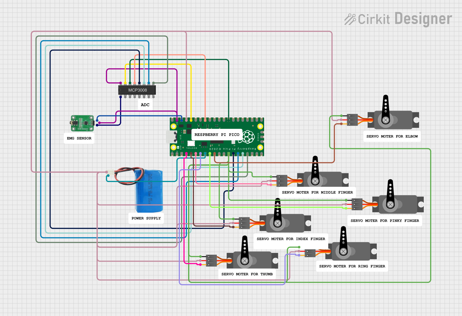
Circuit Documentation
Summary
This circuit involves a Raspberry Pi Pico microcontroller interfacing with multiple servos, a GSR sensor, an MCP3008 ADC, and a 5V battery. The servos are controlled via PWM signals from the Raspberry Pi Pico, while the GSR sensor's output is read through the MCP3008 ADC. The 5V battery powers the entire circuit.
Component List
GSR Sensor
- Pins: GND, VCC, OUT
- Description: Measures the galvanic skin response.
- Purpose: To detect changes in skin conductance.
Servo (x7)
- Pins: GND, VCC, PWM
- Description: Standard servo motor.
- Purpose: To provide controlled rotational movement.
Raspberry Pi Pico
- Pins: 43 GPIO pins
- Description: Microcontroller board based on the RP2040 microcontroller.
- Purpose: To control the servos and read data from the GSR sensor.
5V Battery
- Pins: Positive, Negative
- Description: Power source.
- Purpose: To provide power to the circuit.
MCP3008 8-channel 10-bit ADC
- Pins: Multiple (not named)
- Description: Analog-to-digital converter.
- Purpose: To convert the analog signal from the GSR sensor to a digital signal readable by the Raspberry Pi Pico.
Wiring Details
GSR Sensor
- GND connected to Raspberry Pi Pico pin 38
- VCC connected to MCP3008 and Raspberry Pi Pico pin 39
- OUT connected to MCP3008
Servo 1
- GND connected to common ground
- VCC connected to 5V battery positive
- PWM connected to Raspberry Pi Pico pin 4
Servo 2
- GND connected to common ground
- VCC connected to 5V battery positive
- PWM connected to Raspberry Pi Pico pin 5
Servo 3
- GND connected to common ground
- VCC connected to 5V battery positive
- PWM connected to Raspberry Pi Pico pin 6
Servo 4
- GND connected to common ground
- VCC connected to 5V battery positive
- PWM connected to Raspberry Pi Pico pin 7
Servo 5
- GND connected to common ground
- VCC connected to 5V battery positive
- PWM connected to Raspberry Pi Pico pin 9
Servo 6
- GND connected to common ground
- VCC connected to 5V battery positive
- PWM connected to Raspberry Pi Pico pin 10
Servo 7
- GND connected to common ground
- VCC connected to 5V battery positive
- PWM connected to Raspberry Pi Pico pin 11
Raspberry Pi Pico
- Pin 4 connected to Servo 1 PWM
- Pin 5 connected to Servo 2 PWM
- Pin 6 connected to Servo 3 PWM
- Pin 7 connected to Servo 4 PWM
- Pin 8 connected to 5V battery negative
- Pin 9 connected to Servo 5 PWM
- Pin 10 connected to Servo 6 PWM
- Pin 11 connected to Servo 7 PWM
- Pin 13 connected to common ground
- Pin 14 connected to MCP3008
- Pin 15 connected to MCP3008
- Pin 16 connected to MCP3008
- Pin 17 connected to MCP3008
- Pin 28 connected to MCP3008
- Pin 33 connected to MCP3008
- Pin 36 connected to MCP3008
- Pin 37 connected to 5V battery positive
- Pin 38 connected to GSR Sensor GND
- Pin 39 connected to GSR Sensor VCC
5V Battery
- Positive connected to Servo VCC and Raspberry Pi Pico pin 37
- Negative connected to Raspberry Pi Pico pin 8
MCP3008 8-channel 10-bit ADC
- Connected to Raspberry Pi Pico pins 14, 15, 16, 17, 28, 33, 36
- Connected to GSR Sensor VCC and OUT
Documented Code
sketch.ino
void setup() {
  // put your setup code here, to run once:

}

void loop() {
  // put your main code here, to run repeatedly:

}
documentation.txt