
ESP32-Based Automated Sound System with Motion Detection and Ultrasonic Triggering
View and Edit Project In Cirkit Designer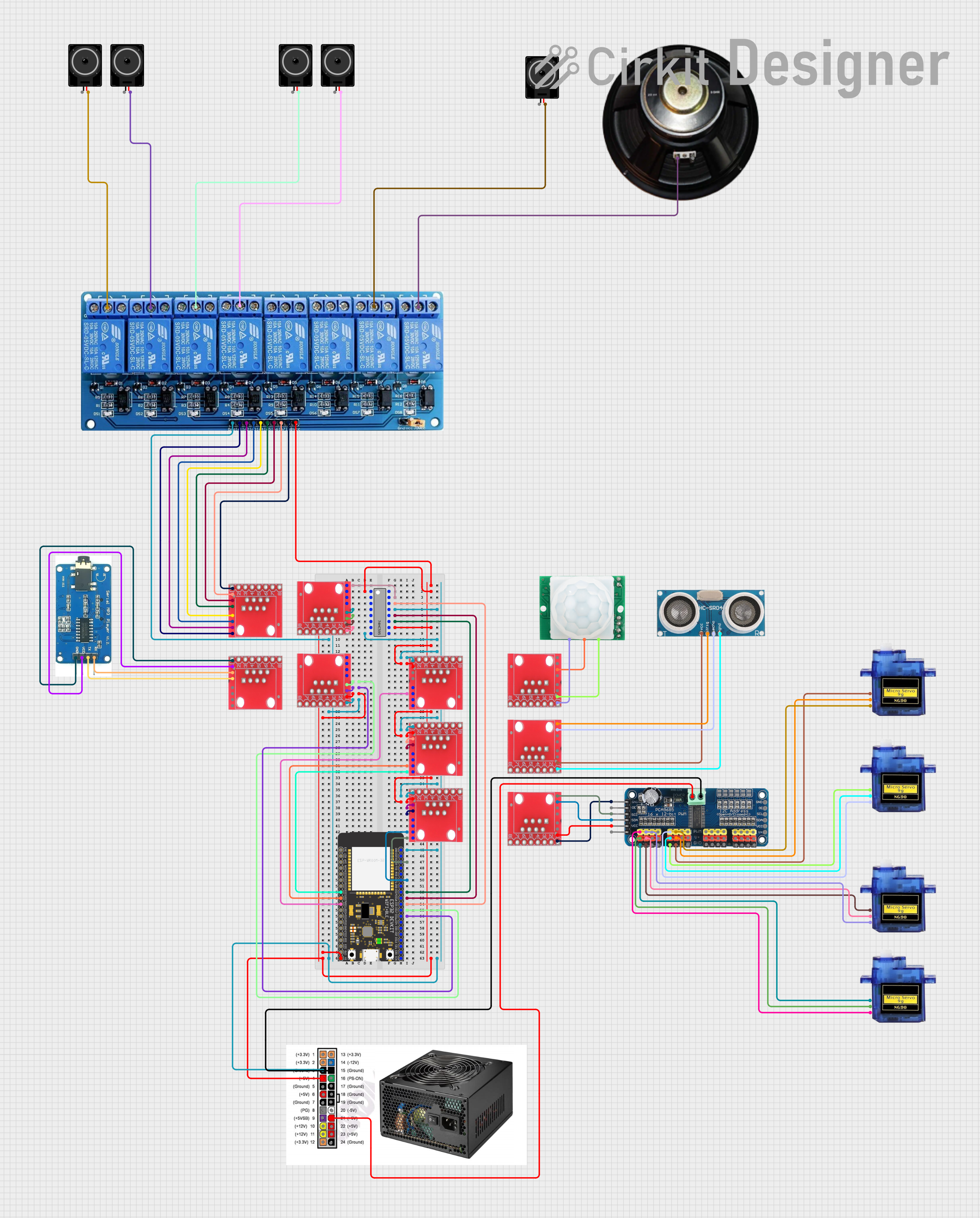
Circuit Documentation
Summary
The circuit in question appears to be a complex system involving communication, sensing, and actuation components. It includes an ESP32 microcontroller for control logic, a 74HC595 shift register for signal expansion, multiple RJ45 connectors for interfacing, an ultrasonic sensor for distance measurement, a motion sensor for detecting movement, a serial MP3 player for audio output, a 16-channel PWM servo driver for controlling servos, micro servos for actuation, a relay module for switching higher power loads, and loudspeakers for audio output. The ATX power supply provides the necessary power for the components.
Component List
RJ45 Connector
- Description: Ethernet connector used for interfacing with various signals in the circuit.
Ultrasonic Sensor
- Description: Sensor used for measuring distances via ultrasonic waves.
Serial MP3 Player
- Description: A module that can play audio files from a storage device.
HC-SR501 Motion Sensor
- Description: A PIR sensor module for detecting motion.
ATX Power Supply
- Description: A power supply unit that provides various voltage levels for the circuit.
Loudspeaker
- Description: An electroacoustic transducer used to produce sound.
16-Channel PWM Servo Driver
- Description: A module that can control up to 16 servos with PWM signal.
ESP32 Wroom
- Description: A powerful microcontroller with Wi-Fi and Bluetooth capabilities.
74HC595 Shift Register
- Description: An 8-bit serial-in, serial or parallel-out shift register with output latches.
Micro Servo 9G
- Description: A small-sized servo motor for precise control.
5V 8-Channel Relay
- Description: A relay module with 8 channels that can be controlled individually.
Wiring Details
RJ45 Connector
- Used for interfacing with various components via Ethernet cables.
Ultrasonic Sensor
- VCC: Connected to a 5V supply.
- Trigger: Connected to an RJ45 connector for signal output.
- Echo: Connected to an RJ45 connector for signal input.
- GND: Connected to the ground.
Serial MP3 Player
- VCC: Connected to a 5V supply.
- GND: Connected to the ground.
- RX: Connected to an RJ45 connector for serial communication.
- TX: Connected to an RJ45 connector for serial communication.
HC-SR501 Motion Sensor
- VCC: Connected to a 5V supply.
- OUT: Connected to an RJ45 connector for signal output.
- GND: Connected to the ground.
ATX Power Supply
- Provides various voltage levels, including 5V and GND, to power the circuit.
Loudspeaker
- Typically connected to an audio output or amplifier.
16-Channel PWM Servo Driver
- V+: Connected to a 5V supply.
- VCC: Connected to a 5V supply.
- SDA: Connected to an RJ45 connector for I2C data.
- SCL: Connected to an RJ45 connector for I2C clock.
- GND: Connected to the ground.
- PWM1-PWM16: Connected to the PWM pins of micro servos.
ESP32 Wroom
- 5V: Connected to a 5V supply.
- GND: Connected to the ground.
- GPIOs: Connected to various components for control signals.
74HC595 Shift Register
- VCC: Connected to a 5V supply.
- GND: Connected to the ground.
- Q0-Q7: Connected to RJ45 connectors for signal output.
- DS (DATA), OE (Enable), ST_CP (RCLK), SH_CP (SRCLK), MR (SRCLR): Connected to the ESP32 for control signals.
Micro Servo 9G
- +5V: Connected to a 5V supply.
- GND: Connected to the ground.
- PWM: Connected to the PWM output from the 16-Channel PWM Servo Driver.
5V 8-Channel Relay
- VCC: Connected to a 5V supply.
- GND: Connected to the ground.
- IN1-IN8: Connected to RJ45 connectors for control signals.
- C, NC, NO: Connected to loudspeakers and other components for switching.
Documented Code
ESP32 Wroom (sketch.ino)
void setup() {
  // put your setup code here, to run once:

}

void loop() {
  // put your main code here, to run repeatedly:

}
ESP32 Wroom (documentation.txt)
(No additional documentation provided for the code)
This documentation provides an overview of the circuit's components, their connections, and the embedded code for the ESP32 microcontroller. Further details may be added to the code section as the implementation progresses.