
Arduino Mega 2560-Based Automated Grinding System with IR Sensor and LCD Display
View and Edit Project In Cirkit Designer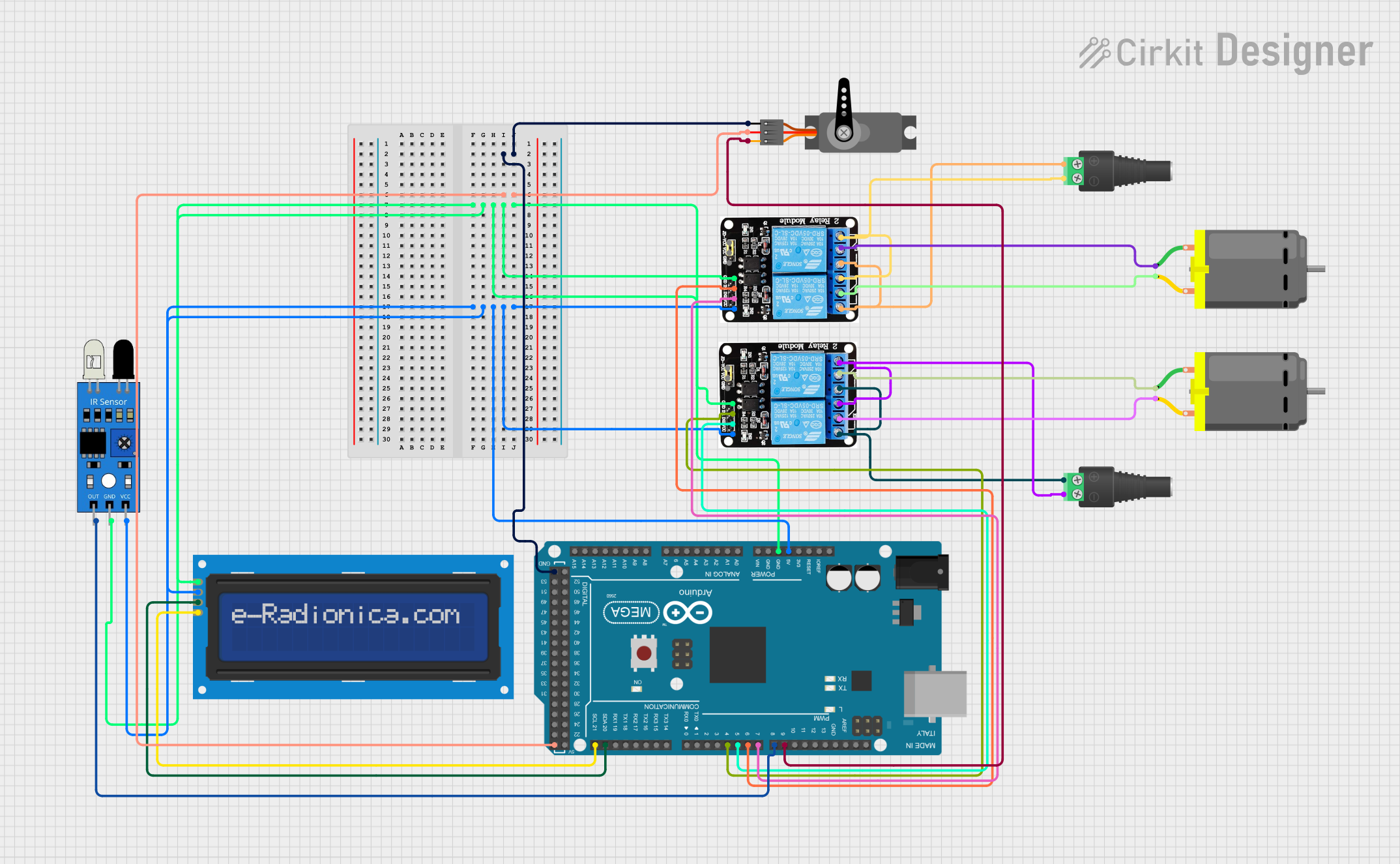
Circuit Documentation
Summary
This circuit is designed to control a grinding process using an Arduino Mega 2560 microcontroller. The system includes various components such as DC motors, IR sensors, relays, an LCD screen, and a servo motor. The Arduino Mega 2560 reads the state of an IR sensor to determine whether to start or stop the grinding process. It also controls the position of a servo motor and displays the status of the grinding process on an LCD screen.
Component List
DC Motor
- Description: A motor that converts electrical energy into mechanical energy.
- Pins: pin 1, pin 2
IR Sensor
- Description: An infrared sensor used to detect objects.
- Pins: out, gnd, vcc
Arduino Mega 2560
- Description: A microcontroller board based on the ATmega2560.
- Pins: IOREF, RESET, 3V3, 5V, GND, VIN, A0-A15, D21/SCL, D20/SDA, D19/RX1, D18/TX1, D17 PWM/RX2, D16 PWM/TX2, D15/RX3, D14/TX3, D0 RX0, D1 TX0, D2-D13 PWM, AREF, SDA, SCL, D22-D53
5V 2-Relay JD-VCC
- Description: A relay module used to control high voltage devices.
- Pins: JD-VCC, VCC, GND, IN1, IN2, NO, COM, NC
LCD Screen 16x2 I2C
- Description: A 16x2 character LCD display with I2C interface.
- Pins: SCL, SDA, VCC, GND
Servo
- Description: A motor that can be positioned to specific angles.
- Pins: GND, VCC, PWM
2.1mm Barrel Jack with Terminal Block
- Description: A power connector for supplying voltage to the circuit.
- Pins: POS, NEG
Wiring Details
DC Motor
- pin 1 connected to COM of 5V 2-Relay JD-VCC
- pin 2 connected to COM of 5V 2-Relay JD-VCC
IR Sensor
- out connected to D8 PWM of Arduino Mega 2560
- gnd connected to GND of Arduino Mega 2560
- vcc connected to 5V of Arduino Mega 2560
Arduino Mega 2560
- GND connected to GND of Servo, LCD Screen 16x2 I2C, 5V 2-Relay JD-VCC, IR Sensor
- 5V connected to VCC of Servo, LCD Screen 16x2 I2C, 5V 2-Relay JD-VCC, IR Sensor
- D21/SCL connected to SCL of LCD Screen 16x2 I2C
- D20/SDA connected to SDA of LCD Screen 16x2 I2C
- D4 PWM connected to IN1 of 5V 2-Relay JD-VCC
- D5 PWM connected to IN2 of 5V 2-Relay JD-VCC
- D6 PWM connected to IN1 of 5V 2-Relay JD-VCC
- D7 PWM connected to IN2 of 5V 2-Relay JD-VCC
- D8 PWM connected to out of IR Sensor
- D9 PWM connected to PWM of Servo
5V 2-Relay JD-VCC
- GND connected to GND of Arduino Mega 2560
- VCC connected to 5V of Arduino Mega 2560
- IN1 connected to D4 PWM of Arduino Mega 2560
- IN2 connected to D5 PWM of Arduino Mega 2560
- COM connected to pin 1 and pin 2 of DC Motor
- NO connected to POS of 2.1mm Barrel Jack with Terminal Block
- NC connected to NEG of 2.1mm Barrel Jack with Terminal Block
LCD Screen 16x2 I2C
- SCL connected to D21/SCL of Arduino Mega 2560
- SDA connected to D20/SDA of Arduino Mega 2560
- VCC connected to 5V of Arduino Mega 2560
- GND connected to GND of Arduino Mega 2560
Servo
- GND connected to GND of Arduino Mega 2560
- VCC connected to 5V of Arduino Mega 2560
- PWM connected to D9 PWM of Arduino Mega 2560
2.1mm Barrel Jack with Terminal Block
- POS connected to NO of 5V 2-Relay JD-VCC
- NEG connected to NC of 5V 2-Relay JD-VCC
Code Documentation
#include <Wire.h>
#include <Servo.h>
#include <LiquidCrystal_I2C.h>

LiquidCrystal_I2C lcd(0x27, 16, 2);
Servo myServo;

void setup()
{
  lcd.begin();
  lcd.backlight();
  lcd.setCursor(0, 0);
  pinMode(4, OUTPUT);
  pinMode(5, OUTPUT);
  pinMode(6, OUTPUT);
  pinMode(7, OUTPUT);
  pinMode(8, INPUT);
  myServo.attach(9);
}

void loop()
{
  int irSensorState = digitalRead(4);
  if (irSensorState == HIGH)
  {
    digitalWrite(2, HIGH);
    digitalWrite(3, HIGH);
    lcd.print("Grinding Process is going on!!");
    delay(120000);
  }
  else
  {
    digitalWrite(2, LOW);
    digitalWrite(3, LOW);
    lcd.print("Grinding Process completed");
  }
  myServo.write(0);
  delay(1000);

  myServo.write(180);
  delay(1000);
}
Code Explanation
Libraries Included:
Wire.h: For I2C communication.Servo.h: For controlling the servo motor.LiquidCrystal_I2C.h: For controlling the LCD screen.
Setup Function:
- Initializes the LCD screen and sets the cursor position.
- Configures pins 4, 5, 6, and 7 as outputs.
- Configures pin 8 as an input.
- Attaches the servo motor to pin 9.
Loop Function:
- Reads the state of the IR sensor connected to pin 4.
- If the IR sensor detects an object, it starts the grinding process by setting pins 2 and 3 to HIGH and displays a message on the LCD screen. The process runs for 120 seconds.
- If the IR sensor does not detect an object, it stops the grinding process by setting pins 2 and 3 to LOW and displays a completion message on the LCD screen.
- The servo motor is moved to 0 degrees, waits for 1 second, then moved to 180 degrees, and waits for another second.