Cirkit Designer
Your all-in-one circuit design IDE
Home /
Project Documentation
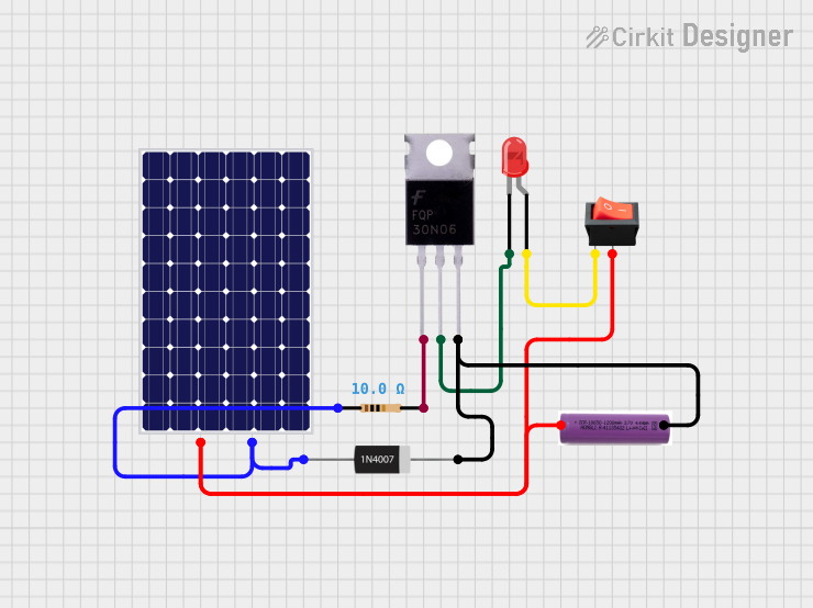
Solar-Powered LED Light with Battery Backup and Rocker Switch Control
Circuit Documentation
Summary of the Circuit
This circuit appears to be a simple power supply and control circuit for an LED, utilizing a solar panel and a battery as power sources. A rocker switch is used to control the power flow, and a MOSFET is likely used as a switch or regulator for the LED. A diode is included, possibly for reverse voltage protection or rectification, and a resistor is in place, presumably to limit current to the LED.
Component List
Solar Panel
- Description: A device that converts light into electrical energy.
- Pins:
+,-
Rocker Switch
- Description: A switch to control the connection of the circuit.
- Pins:
output,input
LED: Two Pin (red)
- Description: A red light-emitting diode.
- Pins:
cathode,anode
3.7v Battery
- Description: A power source providing a voltage of 3.7 volts.
- Pins:
+,-
MOSFET
- Description: A type of transistor used for switching electronic signals.
- Pins:
Gate,Drain,Source
1N4007 Rectifier Diode
- Description: A diode commonly used for rectifying alternating current to direct current.
- Pins:
Cathode,Anode
Resistor
- Description: A passive two-terminal electrical component that implements electrical resistance as a circuit element.
- Pins:
pin1,pin2 - Properties: Resistance: 10 Ohms
Wiring Details
Solar Panel
+connected to theoutputof the Rocker Switch and+of the 3.7v Battery.-connected to theAnodeof the 1N4007 Rectifier Diode.
Rocker Switch
outputconnected to the+of the Solar Panel and+of the 3.7v Battery.inputconnected to theanodeof the LED: Two Pin (red).
LED: Two Pin (red)
anodeconnected to theinputof the Rocker Switch.cathodeconnected to theDrainof the MOSFET.
3.7v Battery
+connected to theoutputof the Rocker Switch and+of the Solar Panel.-connected to theSourceof the MOSFET andCathodeof the 1N4007 Rectifier Diode.
MOSFET
Gateconnected topin2of the Resistor.Drainconnected to thecathodeof the LED: Two Pin (red).Sourceconnected to the-of the 3.7v Battery andCathodeof the 1N4007 Rectifier Diode.
1N4007 Rectifier Diode
Anodeconnected to the-of the Solar Panel.Cathodeconnected to theSourceof the MOSFET and-of the 3.7v Battery.
Resistor
pin1connected to theAnodeof the 1N4007 Rectifier Diode.pin2connected to theGateof the MOSFET.
Documented Code
There is no microcontroller code provided for this circuit. If a microcontroller is added to the circuit in the future, the code will be documented in this section.