
Battery-Powered IR Sensor Controlled Water Pump and Solenoid Valve System
View and Edit Project In Cirkit Designer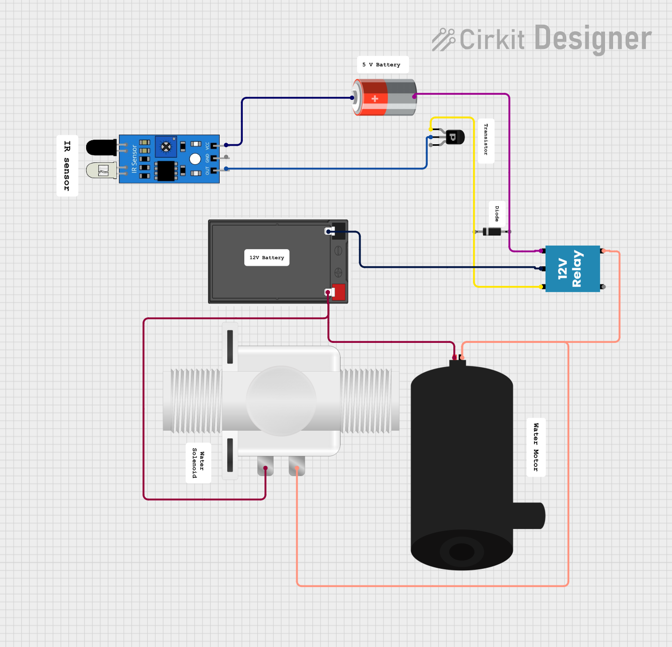
Circuit Documentation
Summary
This document provides a detailed overview of a circuit that includes various components such as batteries, a solenoid valve, a PNP transistor, an IR sensor, a relay, a water pump, and a diode. The circuit is designed to control the operation of a water pump and a solenoid valve based on the input from an IR sensor. The circuit is powered by a 5V battery and an additional battery.
Component List
5V Battery
- Pins: +, -
- Description: Provides 5V power supply to the circuit.
- Purpose: Powers the IR sensor and the relay.
Battery
- Pins: +, -
- Description: Provides additional power supply to the circuit.
- Purpose: Powers the water pump and the solenoid valve.
Plastic Solenoid Valve
- Pins: pin1, pin2
- Description: Controls the flow of liquid.
- Purpose: Operates based on the relay's output.
PNP Transistor (EBC)
- Pins: emitter, base, collector
- Description: Acts as a switch to control the relay.
- Purpose: Switches the relay based on the IR sensor's output.
IR Sensor
- Pins: out, gnd, vcc
- Description: Detects infrared signals.
- Purpose: Provides input to the transistor to control the relay.
12V Relay
- Pins: +, -, C, NC, NO
- Description: Electromechanical switch.
- Purpose: Controls the water pump and solenoid valve based on the transistor's output.
Water Pump
- Pins: positive, negative
- Description: Pumps water.
- Purpose: Operates based on the relay's output.
Diode
- Pins: cathode, anode
- Description: Allows current to flow in one direction.
- Purpose: Protects the circuit from reverse voltage.
Wiring Details
5V Battery
- + Pin: Connected to the vcc pin of the IR sensor.
- - Pin: Connected to the - pin of the 12V relay.
Battery
- + Pin: Connected to the positive pin of the water pump and pin1 of the solenoid valve.
- - Pin: Connected to the C pin of the 12V relay.
Plastic Solenoid Valve
- pin1: Connected to the + pin of the battery.
- pin2: Connected to the NO pin of the 12V relay.
PNP Transistor (EBC)
- Emitter: Connected to the + pin of the 12V relay.
- Base: Connected to the out pin of the IR sensor.
- Collector: Not connected in this circuit.
IR Sensor
- out: Connected to the base pin of the PNP transistor.
- gnd: Not connected in this circuit.
- vcc: Connected to the + pin of the 5V battery.
12V Relay
- + Pin: Connected to the emitter pin of the PNP transistor.
- - Pin: Connected to the - pin of the 5V battery.
- C Pin: Connected to the - pin of the battery.
- NC Pin: Not connected in this circuit.
- NO Pin: Connected to the negative pin of the water pump and pin2 of the solenoid valve.
Water Pump
- Positive Pin: Connected to the + pin of the battery.
- Negative Pin: Connected to the NO pin of the 12V relay.
Diode
- Cathode: Not connected in this circuit.
- Anode: Not connected in this circuit.
Code
There is no microcontroller code provided for this circuit.
This document provides a comprehensive overview of the circuit, including a summary, component list, wiring details, and code documentation. Each component is described in detail, and the wiring connections are clearly outlined to ensure proper assembly and operation of the circuit.