Arduino UNO Controlled Interactive Display with Joystick and Buzzer Feedback
Circuit Documentation
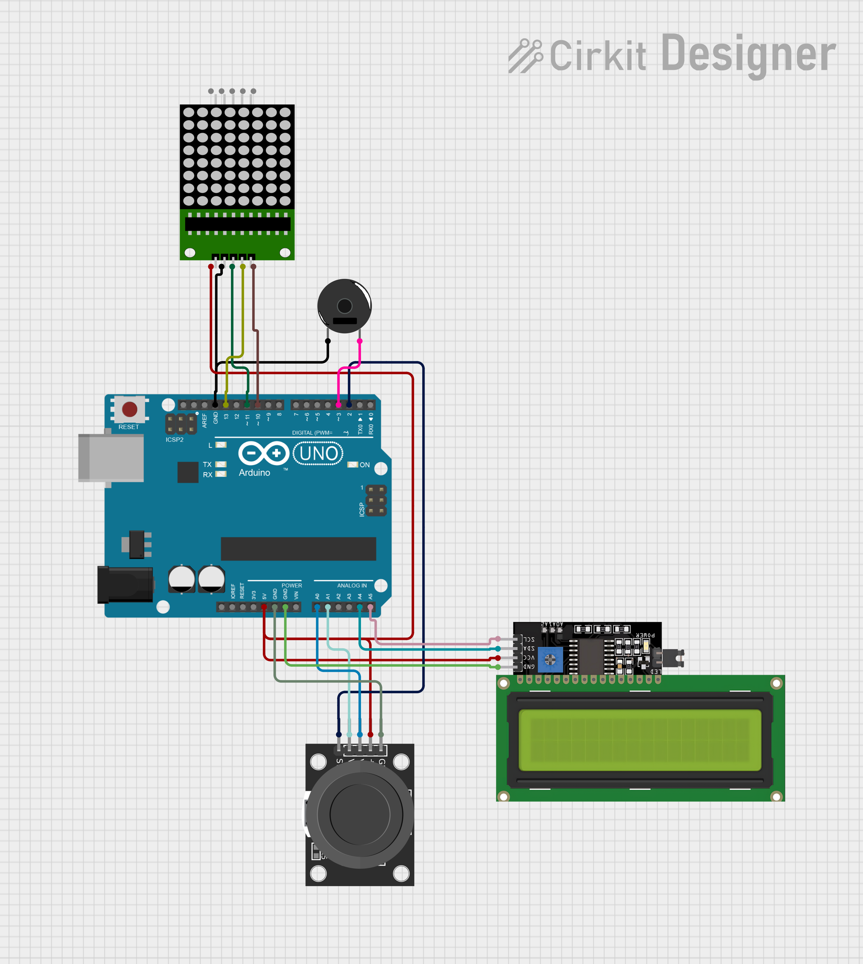
Summary
This circuit integrates various components controlled by an Arduino UNO microcontroller to perform a set of functions. The components include an 8x8 LED matrix, an LCD Display (16x4) with I2C interface, a KY-023 Dual Axis Joystick Module, and a Piezo Buzzer. The Arduino UNO serves as the central processing unit, interfacing with the input module (joystick), output modules (LED matrix and LCD display), and providing feedback through the Piezo Buzzer. The circuit is designed to be powered by the Arduino's 5V output, with ground connections appropriately distributed.
Component List
8x8 LED Matrix
- Description: A matrix of 64 LEDs arranged in an 8x8 grid, used for displaying patterns or characters.
- Pins: vcc, DIN, clk, CS, Gnd
LCD Display 16x4 I2C
- Description: A 16-character by 4-line liquid crystal display with an I2C interface for displaying text.
- Pins: SCL, SDA, VCC, GND
KY-023 Dual Axis Joystick Module
- Description: A joystick with two axes of control, providing analog input to the Arduino.
- Pins: GND, +5V, VRx, VRy, SW
Arduino UNO
- Description: A microcontroller board based on the ATmega328P, with digital and analog I/O pins.
- Pins: IOREF, Reset, 3.3V, 5V, GND, Vin, A0-A5, SCL, SDA, AREF, D0-D13
Piezo Buzzer
- Description: An electronic device that emits a tone when voltage is applied.
- Pins: pin 1, pin 2
Wiring Details
8x8 LED Matrix
- VCC: Connected to Arduino UNO 5V
- DIN: Connected to Arduino UNO Digital Pin 11 (D11)
- CLK: Connected to Arduino UNO Digital Pin 13 (D13)
- CS: Connected to Arduino UNO Digital Pin 10 (D10)
- GND: Connected to Arduino UNO GND
LCD Display 16x4 I2C
- SCL: Connected to Arduino UNO Analog Pin 5 (A5)
- SDA: Connected to Arduino UNO Analog Pin 4 (A4)
- VCC: Connected to Arduino UNO 5V
- GND: Connected to Arduino UNO GND
KY-023 Dual Axis Joystick Module
- +5V: Connected to Arduino UNO 5V
- GND: Connected to Arduino UNO GND
- VRx: Connected to Arduino UNO Analog Pin 0 (A0)
- VRy: Connected to Arduino UNO Analog Pin 1 (A1)
- SW: Connected to Arduino UNO Digital Pin 2 (D2)
Piezo Buzzer
- Pin 1: Connected to Arduino UNO GND
- Pin 2: Connected to Arduino UNO Digital Pin 3 (D3)
Documented Code
void setup() {
  // put your setup code here, to run once:

}

void loop() {
  // put your main code here, to run repeatedly:

}
The provided code is a template for the Arduino UNO microcontroller. The setup() function is intended for initialization code that runs once, such as configuring pin modes. The loop() function contains the main code that will run repeatedly, which is where the logic for reading inputs, controlling outputs, and interfacing with the components will be implemented. Additional code is required to fully utilize the connected components and perform the desired functions of the circuit.