ESP8266 NodeMCU-Based Weather Monitoring Station with LCD Display
Circuit Documentation
Summary
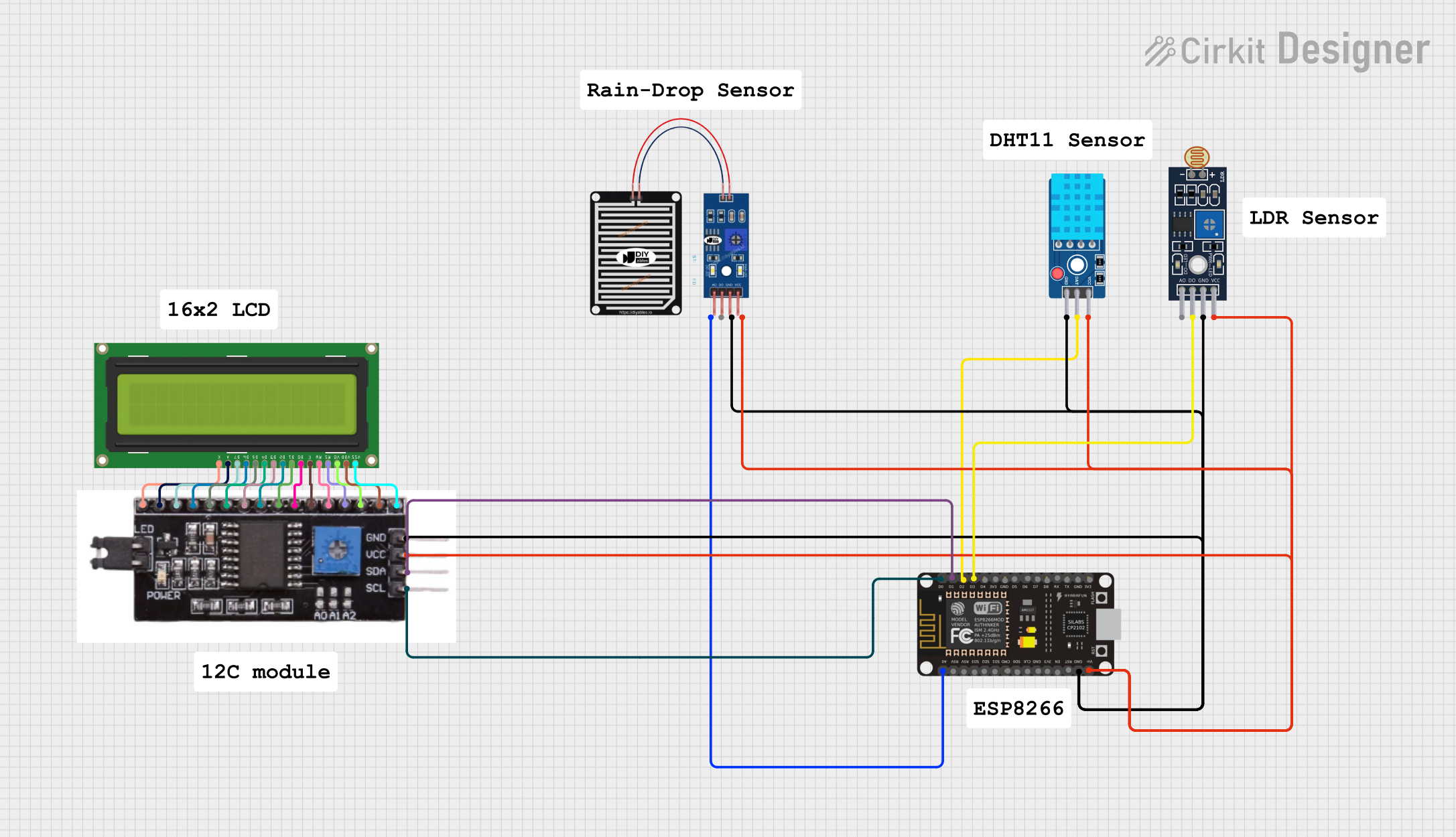
The circuit in question is designed to interface a variety of sensors and an LCD display with an ESP8266 NodeMCU microcontroller. The sensors include a DHT11 temperature and humidity sensor, a rain sensor, and an LDR light sensor with an LM393 comparator. The LCD display is connected via an I2C module to reduce the number of GPIO pins required from the ESP8266. The circuit is likely intended for environmental monitoring, with the capability to display sensor readings and possibly send data over a network using the ESP8266's Wi-Fi capabilities.
Component List
DHT11 Sensor V2
- Pins: GND, DAT, VCC
- Description: A digital temperature and humidity sensor that provides calibrated digital output.
RAIN SENSOR
- Pins: AO, DO, GRD, VCC
- Description: An analog and digital sensor for detecting rain or water level.
Sensor LDR LM393
- Pins: A0, D0, GND, VCC
- Description: A light sensor module that includes an LDR (Light Dependent Resistor) and an LM393 comparator for analog or digital signals.
LCD Display 16x2
- Pins: LEDK, LEDA, DB7-DB0, E, RW, RS, VO, VDD, VSS
- Description: A 16x2 character LCD display for showing text or numbers.
ESP8266 NodeMCU
- Pins: D0-D8, RX, TX, A0, RSV, SD3-SD0, CLK, EN, RST, VIN, 3V3, GND
- Description: A Wi-Fi capable microcontroller with a variety of digital and analog pins for interfacing with sensors, actuators, and communication modules.
I2C Module
- Pins: VSS, VO, RS, RW, E, DB0-DB7, LEDA, LEDK, GND, VCC, SDA, SCL, VDD
- Description: An interface module that allows for I2C communication between the ESP8266 and the LCD display, reducing the number of required GPIO pins.
Wiring Details
DHT11 Sensor V2
- GND: Connected to ESP8266 NodeMCU GND
- DAT: Connected to ESP8266 NodeMCU D2
- VCC: Connected to ESP8266 NodeMCU VIN
RAIN SENSOR
- AO: Connected to ESP8266 NodeMCU A0
- DO: Not connected
- GRD: Connected to ESP8266 NodeMCU GND
- VCC: Connected to ESP8266 NodeMCU VIN
Sensor LDR LM393
- A0: Not connected
- D0: Connected to ESP8266 NodeMCU D3
- GND: Connected to ESP8266 NodeMCU GND
- VCC: Connected to ESP8266 NodeMCU VIN
LCD Display 16x2
- Connected via I2C Module
ESP8266 NodeMCU
- D0: Connected to I2C Module SCL
- D1: Connected to I2C Module SDA
- D2: Connected to DHT11 Sensor V2 DAT
- D3: Connected to Sensor LDR LM393 D0
- A0: Connected to RAIN SENSOR AO
- GND: Common ground with all sensors and I2C Module
- VIN: Power supply to all sensors and I2C Module
I2C Module
- SCL: Connected to ESP8266 NodeMCU D0
- SDA: Connected to ESP8266 NodeMCU D1
- GND: Connected to ESP8266 NodeMCU GND
- VCC: Connected to ESP8266 NodeMCU VIN
- All other pins: Directly connected to corresponding pins on the LCD Display 16x2
Documented Code
No code has been provided for the microcontroller. Typically, the code would initialize the sensors, read data from them, and display the information on the LCD screen. It would also handle any communication over Wi-Fi if the application requires remote monitoring or data logging.