
Arduino 101 Smart Home Automation with Relay Control and Current Sensing
View and Edit Project In Cirkit Designer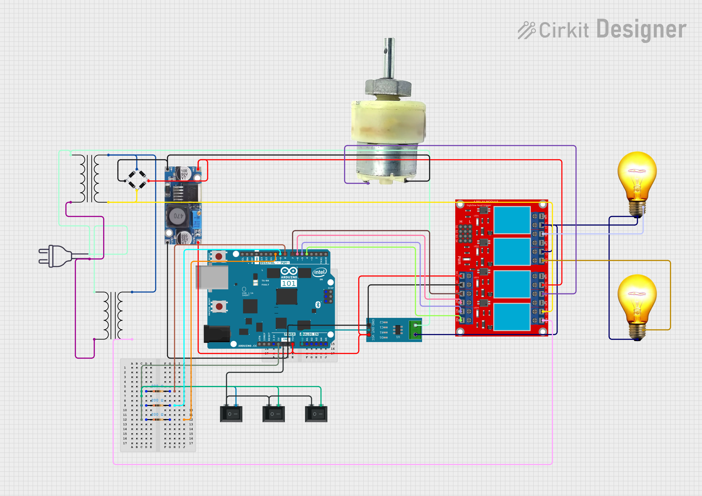
Circuit Documentation
Summary
This circuit involves an Arduino 101 microcontroller interfacing with a 4-channel relay module, various resistors, a current sensor, a step-down buck converter, a bridge rectifier, power transformers, AC bulbs, a 12V geared motor, and rocker switches. The circuit is designed to control AC and DC loads through relays and monitor current using a current sensor. The Arduino 101 is programmed to manage these components.
Component List
Arduino 101
- Description: Microcontroller board based on the Intel Curie module.
- Pins: A5/SCL, A4/SDA, AREF, GND, D13/SCK, D12/MISO, D11 PWM/MOSI, D10 PWM/SS, D9 PWM, D8, D7, D6 PWM, D5 PWM, D4, D3 PWM, D2, D1/TX, D0/RX, AIN, ioref, RESET, 3V3, 5V, VIN, A0, A1, A2, A3, ICSP MISO, ICSP SCK, ICSP MOSI
4 Channel Relay Module
- Description: Relay module to control high voltage devices.
- Pins: N.O. 4, COM 4, N.C. 4, N.O. 3, COM 3, N.C. 3, N.O. 2, COM 2, N.C. 2, N.O. 1, COM 1, N.C. 1, Pin 13, Pin 14, Pin 15, Pin 16, Pin 17, Pin 18, Pin 19, Pin 20, Pin 21, Pin 22, Pin 23, Pin 24, VCC+, VCC- (GND), IN 1, IN 2, IN 3, IN 4
Power Transformer
- Description: Transformer to step down AC voltage.
- Pins: 1 - Primary, 3 - Secondary, 2 - Primary, 4 - Secondary
Power 220V
- Description: AC power source.
- Pins: hot wire, neutral wire
AC Bulb
- Description: Standard AC light bulb.
- Pins: P, N
Rocker Switch (SPST)
- Description: Single Pole Single Throw switch.
- Pins: 1, 2
Step Down Buck Converter
- Description: DC-DC converter to step down voltage.
- Pins: IN +, IN - GND, OUT +, OUT - GND
Bridge Rectifier
- Description: Converts AC to DC.
- Pins: Source_in-, source_out-, source_out+, source_in+
12V Geared Motor
- Description: DC motor with gear reduction.
- Pins: Terminal 1, Terminal 2
Current Sensor 5A
- Description: Sensor to measure current up to 5A.
- Pins: 1, 2, GND, OUT, VCC
Resistor (200 Ohms)
- Description: Resistor with 200 Ohms resistance.
- Pins: pin1, pin2
Wiring Details
Arduino 101
- D10 PWM/SS connected to Resistor pin2
- D9 PWM connected to Resistor pin2
- D8 connected to Resistor pin2
- D7 connected to 4 Channel Relay Module IN 1
- D6 PWM connected to 4 Channel Relay Module IN 2
- D5 PWM connected to 4 Channel Relay Module IN 3
- D4 connected to 4 Channel Relay Module IN 4
- 5V connected to Resistor pin1 and Resistor pin1
- GND connected to Rocker Switch 1, Rocker Switch 1, Rocker Switch 1, Current Sensor 5A GND, 4 Channel Relay Module VCC- (GND), Step Down Buck Converter OUT - GND
- VIN connected to Step Down Buck Converter OUT +
- A0 connected to Current Sensor 5A OUT
- 3V3 connected to Arduino 101 5V, Arduino 101 GND, Arduino 101 GND, Arduino 101 VIN, Current Sensor 5A VCC, 4 Channel Relay Module VCC+
4 Channel Relay Module
- IN 1 connected to Arduino 101 D7
- IN 2 connected to Arduino 101 D6 PWM
- IN 3 connected to Arduino 101 D5 PWM
- IN 4 connected to Arduino 101 D4
- VCC- (GND) connected to Current Sensor 5A GND, Arduino 101 GND, Step Down Buck Converter OUT - GND
- VCC+ connected to Arduino 101 3V3
- N.O. 4 connected to Power Transformer 4 - Secondary
- COM 4 connected to Power Transformer 4 - Secondary, Bridge Rectifier source_in+
- N.O. 3 connected to 12V Geared Motor Terminal 1
- COM 3 connected to Bridge Rectifier source_out+, Step Down Buck Converter IN +
- N.O. 2 connected to AC Bulb N
- COM 2 connected to AC Bulb P, Current Sensor 5A 1, 4 Channel Relay Module COM 1
- N.O. 1 connected to AC Bulb N
Power Transformer
- 1 - Primary connected to Power 220V neutral wire, Current Sensor 5A 2, Power Transformer 1 - Primary
- 2 - Primary connected to Power 220V hot wire, Power Transformer 2 - Primary
- 3 - Secondary connected to Bridge Rectifier Source_in-, Power Transformer 3 - Secondary
- 4 - Secondary connected to 4 Channel Relay Module N.O. 4, Power Transformer 4 - Secondary
Resistor
- pin2 connected to Arduino 101 D10 PWM/SS
- pin2 connected to Arduino 101 D9 PWM
- pin2 connected to Arduino 101 D8
- pin1 connected to Resistor pin1, Arduino 101 5V
- pin1 connected to Rocker Switch 2
Rocker Switch (SPST)
- 1 connected to Arduino 101 GND, Rocker Switch 1, Rocker Switch 1
- 2 connected to Resistor pin1
Current Sensor 5A
- GND connected to 4 Channel Relay Module VCC- (GND), Arduino 101 GND, Step Down Buck Converter OUT - GND
- OUT connected to Arduino 101 A0
- VCC connected to Arduino 101 3V3
- 1 connected to AC Bulb P, AC Bulb P, 4 Channel Relay Module COM 1, 4 Channel Relay Module COM 2
- 2 connected to Power Transformer 1 - Primary
Step Down Buck Converter
- OUT - GND connected to Current Sensor 5A GND, 4 Channel Relay Module VCC- (GND), Arduino 101 GND
- OUT + connected to Arduino 101 VIN
- IN + connected to Bridge Rectifier source_out+, 4 Channel Relay Module COM 3
- IN - GND connected to 12V Geared Motor Terminal 2, Bridge Rectifier source_out-
Bridge Rectifier
- Source_in- connected to Power Transformer 3 - Secondary
- source_out- connected to 12V Geared Motor Terminal 2, Step Down Buck Converter IN - GND
- source_out+ connected to 4 Channel Relay Module COM 3, Step Down Buck Converter IN +
- source_in+ connected to Power Transformer 4 - Secondary, 4 Channel Relay Module COM 4
12V Geared Motor
- Terminal 1 connected to 4 Channel Relay Module N.O. 3
- Terminal 2 connected to Bridge Rectifier source_out-, Step Down Buck Converter IN - GND
AC Bulb
- N connected to 4 Channel Relay Module N.O. 2
- P connected to AC Bulb P, Current Sensor 5A 1, 4 Channel Relay Module COM 1, 4 Channel Relay Module COM 2
- N connected to 4 Channel Relay Module N.O. 1
Documented Code
Arduino 101 Code
void setup() {
  // put your setup code here, to run once:

}

void