
Wi-Fi Controlled Dual DC Motor Robot with IR Sensors and ESP8266
View and Edit Project In Cirkit Designer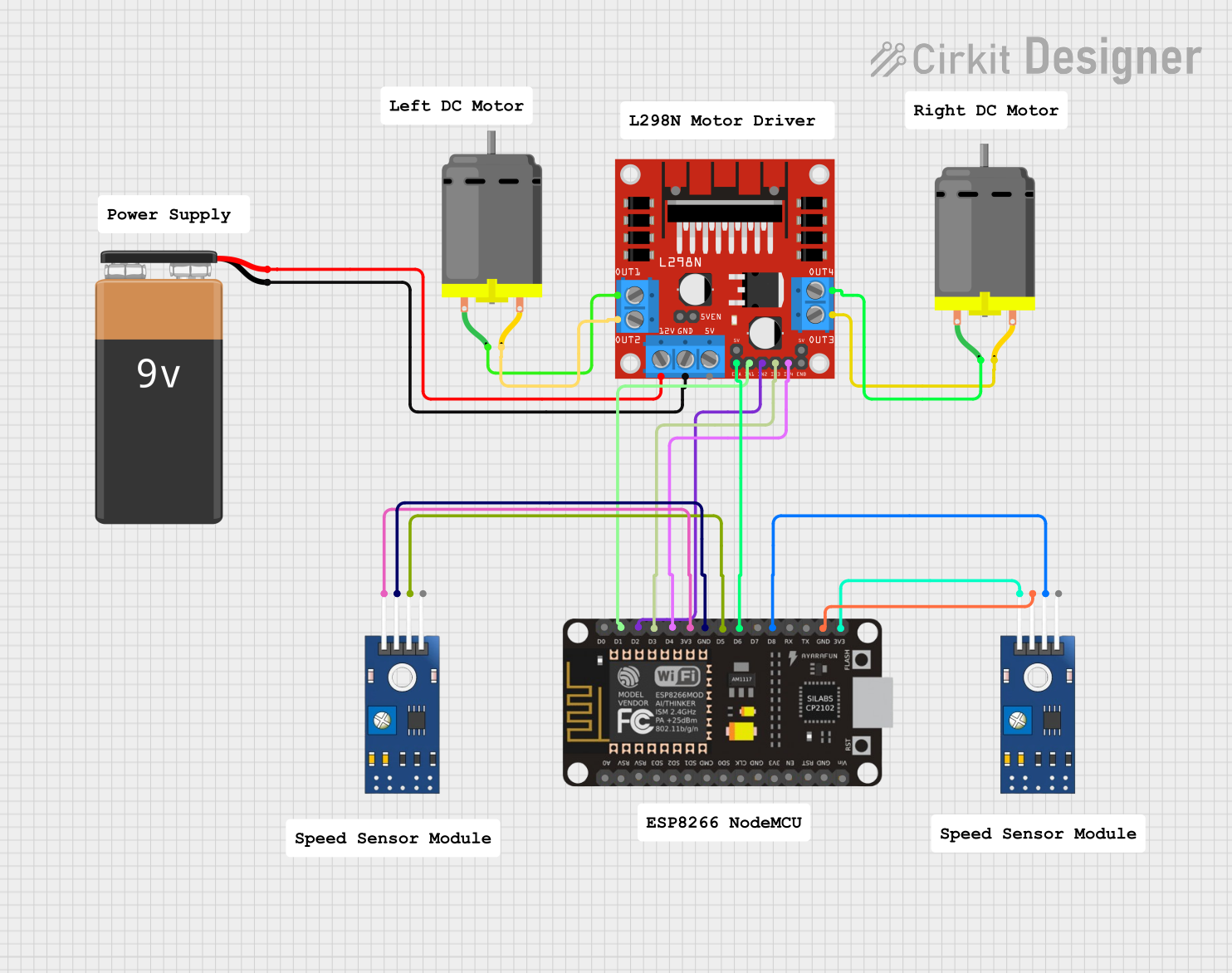
Circuit Documentation
Summary
This document provides a detailed overview of a circuit that includes a 9V battery, an L298N DC motor driver, an ESP8266 NodeMCU, two TCRT 5000 IR sensors, and two DC motors. The circuit is designed to control the DC motors using the motor driver, with the ESP8266 NodeMCU serving as the microcontroller. The IR sensors are used for detecting obstacles or line tracking.
Component List
9V Battery
- Description: Provides power to the circuit.
- Pins: +, -
L298N DC Motor Driver
- Description: Controls the DC motors.
- Pins: OUT1, OUT2, 12V, GND, 5V, OUT3, OUT4, 5V-ENA-JMP-I, 5V-ENA-JMP-O, +5V-J1, +5V-J2, ENA, IN1, IN2, IN3, IN4, ENB
ESP8266 NodeMCU
- Description: Microcontroller for controlling the motor driver and reading sensor data.
- Pins: D0, D1, D2, D3, D4, 3V3, GND, D5, D6, D7, D8, RX, TX, A0, RSV, SD3, SD2, SD1, CMD, SD0, CLK, EN, RST, VIN
TCRT 5000 IR Sensor
- Description: Infrared sensor for obstacle detection or line tracking.
- Pins: VCC, GND, DO, AO
DC Motor
- Description: Actuator for mechanical movement.
- Pins: pin 1, pin 2
Wiring Details
9V Battery
- + connected to 12V of L298N DC Motor Driver
- - connected to GND of L298N DC Motor Driver
L298N DC Motor Driver
- OUT1 connected to pin 1 of DC Motor 1
- OUT2 connected to pin 2 of DC Motor 1
- OUT3 connected to pin 2 of DC Motor 2
- OUT4 connected to pin 1 of DC Motor 2
- ENA connected to D6 of ESP8266 NodeMCU
- IN1 connected to D1 of ESP8266 NodeMCU
- IN2 connected to D2 of ESP8266 NodeMCU
- IN3 connected to D3 of ESP8266 NodeMCU
- IN4 connected to D4 of ESP8266 NodeMCU
ESP8266 NodeMCU
- 3V3 connected to VCC of TCRT 5000 IR Sensor 1
- GND connected to GND of TCRT 5000 IR Sensor 1
- D5 connected to DO of TCRT 5000 IR Sensor 1
- 3V3 connected to VCC of TCRT 5000 IR Sensor 2
- GND connected to GND of TCRT 5000 IR Sensor 2
- D8 connected to DO of TCRT 5000 IR Sensor 2
TCRT 5000 IR Sensor 1
- VCC connected to 3V3 of ESP8266 NodeMCU
- GND connected to GND of ESP8266 NodeMCU
- DO connected to D5 of ESP8266 NodeMCU
TCRT 5000 IR Sensor 2
- VCC connected to 3V3 of ESP8266 NodeMCU
- GND connected to GND of ESP8266 NodeMCU
- DO connected to D8 of ESP8266 NodeMCU
DC Motor 1
- pin 1 connected to OUT1 of L298N DC Motor Driver
- pin 2 connected to OUT2 of L298N DC Motor Driver
DC Motor 2
- pin 1 connected to OUT4 of L298N DC Motor Driver
- pin 2 connected to OUT3 of L298N DC Motor Driver
Code
No code was provided for this circuit.