
Solar-Powered Environmental Monitoring Station with Data Logging and Remote Access
View and Edit Project In Cirkit Designer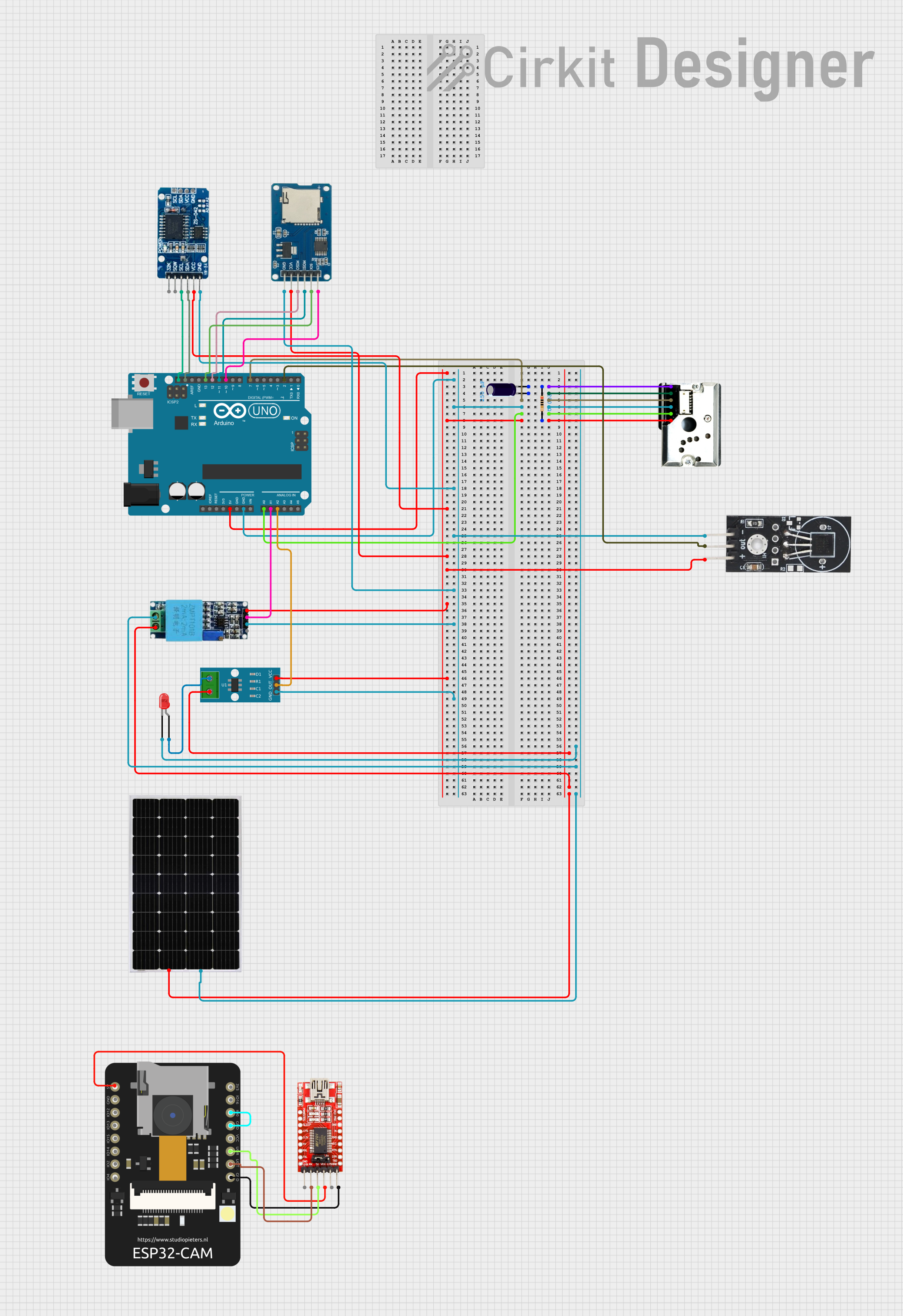
Circuit Documentation
Summary
This circuit integrates various sensors, a microcontroller, and other components to perform multiple functions. The central processing unit is an Arduino UNO, which interfaces with a dust sensor, temperature sensor, voltage sensor, current sensor, real-time clock, micro SD card module, and an ESP32 CAM module for additional connectivity and functionalities. The circuit also includes passive components like a resistor and an electrolytic capacitor for signal conditioning and power management. An FTDI programmer is used for programming the ESP32 CAM module. The circuit is designed to monitor environmental parameters, manage data logging, and potentially communicate with other devices or networks.
Component List
- Arduino UNO: A microcontroller board based on the ATmega328P, featuring digital and analog I/O pins.
- GP2Y1010AU0F: An optical dust sensor for detecting fine particle concentration in the air.
- Electrolytic Capacitor: A capacitor typically used for filtering and power smoothing applications.
- Resistor: A passive two-terminal electrical component that implements electrical resistance as a circuit element.
- DS18B20 Temperature Sensor: A digital temperature sensor that provides 9-bit to 12-bit Celsius temperature measurements.
- Voltage Sensor: A device that can measure the electrical potential difference between two points in an electric circuit.
- Solar Panel: A panel designed to absorb the sun's rays as a source of energy for generating electricity.
- ACS712 Current Sensor 5A 20A 30A: A hall-effect-based linear current sensor.
- LED (red): A two-pin light-emitting diode that emits red light when powered.
- RTC DS3231: A real-time clock module that provides accurate timekeeping with a temperature-compensated crystal oscillator.
- Micro SD Card Module: A module that allows micro SD cards to be read and written using a microcontroller.
- ESP32 CAM: A small camera module with Wi-Fi and Bluetooth capabilities.
- FTDI Programmer: A USB to serial converter for programming devices like the ESP32 CAM.
Wiring Details
Arduino UNO
- Digital Pin 7 connected to GP2Y1010AU0F LED.
- Analog Pin A0 connected to GP2Y1010AU0F Vout.
- Analog Pin A1 connected to Voltage Sensor Out.
- Analog Pin A2 connected to ACS712 Current Sensor OUT.
- I2C SCL connected to RTC DS3231 SCL.
- I2C SDA connected to RTC DS3231 SDA.
- SPI SCK connected to Micro SD Card Module sck.
- SPI MISO connected to Micro SD Card Module miso.
- SPI MOSI connected to Micro SD Card Module mosi.
- SPI SS connected to Micro SD Card Module cs.
- Digital Pin 2 connected to DS18B20 Temperature Sensor OUT.
- 5V pin connected to several components' VCC pins.
- GND pin connected to several components' GND pins.
GP2Y1010AU0F Dust Sensor
- V-LED connected to Electrolytic Capacitor (+) and Resistor (pin1).
- LED-GND connected to Electrolytic Capacitor (-).
- LED connected to Arduino UNO Digital Pin 7.
- S-GND connected to Arduino UNO GND.
- Vout connected to Arduino UNO Analog Pin A0.
- VCC connected to Resistor (pin2) and Arduino UNO 5V.
Electrolytic Capacitor
- (+) connected to GP2Y1010AU0F V-LED and Resistor (pin1).
- (-) connected to GP2Y1010AU0F LED-GND.
Resistor
- Pin1 connected to Electrolytic Capacitor (+) and GP2Y1010AU0F V-LED.
- Pin2 connected to GP2Y1010AU0F VCC and Arduino UNO 5V.
DS18B20 Temperature Sensor
- GND connected to Arduino UNO GND.
- VCC connected to Arduino UNO 5V.
- OUT connected to Arduino UNO Digital Pin 2.
Voltage Sensor
- Ground connected to LED (red) cathode and Solar Panel (-).
- Phase connected to ACS712 Current Sensor pin 2 and Solar Panel (+).
- Vcc connected to Arduino UNO 5V.
- Out connected to Arduino UNO Analog Pin A1.
- Gnd connected to Arduino UNO GND.
Solar Panel
- (+) connected to Voltage Sensor Phase and ACS712 Current Sensor pin 2.
- (-) connected to LED (red) cathode.
ACS712 Current Sensor
- Pin 1 connected to LED (red) anode.
- Pin 2 connected to Voltage Sensor Phase and Solar Panel (+).
- GND connected to Arduino UNO GND.
- OUT connected to Arduino UNO Analog Pin A2.
- VCC connected to Arduino UNO 5V.
LED (red)
- Cathode connected to Voltage Sensor Ground and Solar Panel (-).
- Anode connected to ACS712 Current Sensor pin 1.
RTC DS3231
- SCL connected to Arduino UNO SCL.
- SDA connected to Arduino UNO SDA.
- VCC connected to Arduino UNO 5V.
- GND connected to Arduino UNO GND.
Micro SD Card Module
- SCK connected to Arduino UNO SPI SCK.
- MISO connected to Arduino UNO SPI MISO.
- MOSI connected to Arduino UNO SPI MOSI.
- CS connected to Arduino UNO SPI SS.
- VCC connected to Arduino UNO 5V.
- GND connected to Arduino UNO GND.
ESP32 CAM
- 5V connected to FTDI Programmer VCC.
- GND connected to FTDI Programmer GND and ESP32 CAM GPIO0.
- GPIO3 / RX connected to FTDI Programmer TX.
- GPIO1 / TX connected to FTDI Programmer RX.
FTDI Programmer
- VCC connected to ESP32 CAM 5V.
- TX connected to ESP32 CAM GPIO3 / RX.
- RX connected to ESP32 CAM GPIO1 / TX.
- GND connected to ESP32 CAM GND.
Documented Code
Arduino UNO Code (sketch.ino)
void setup() {
  // put your setup code here, to run once:

}

void loop() {
  // put your main code here, to run repeatedly:

}
Note: The code provided for the Arduino UNO is a template and does not contain any functional code. It needs to be populated with the logic to interact with the connected sensors and modules.