ESP32-Based Environmental Monitoring and Watering System

Circuit Documentation
Summary
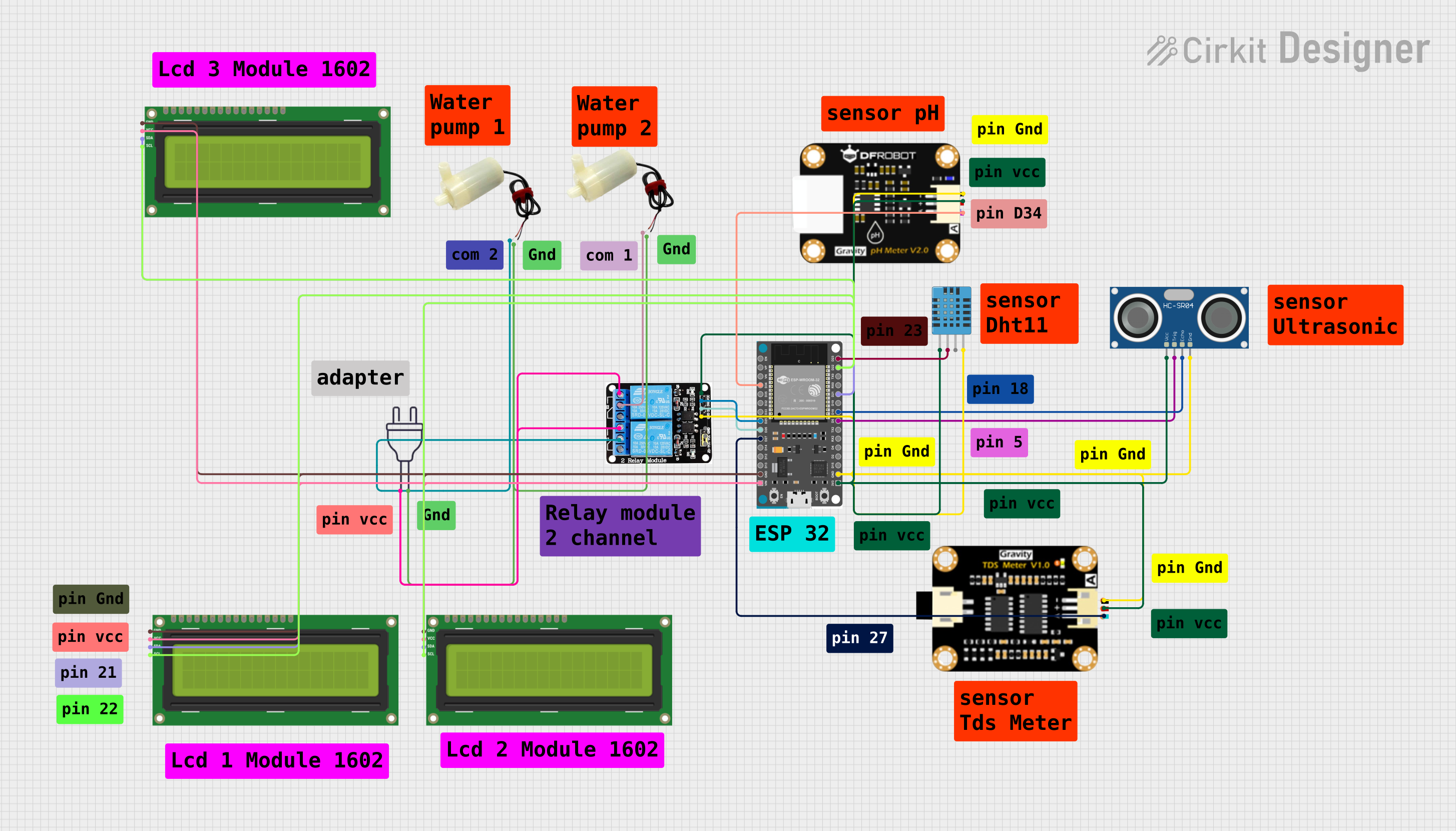
This circuit is designed to interface various sensors and actuators with an ESP32 Devkit V1 microcontroller. The sensors include a DHT11 humidity and temperature sensor, an HC-SR04 ultrasonic sensor, a pH degree sensor module, and a TDS (Total Dissolved Solids) sensor module. The circuit also includes a 5V 2-Relay module to control two 5V mini water pumps and three I2C LCD 16x2 screens for display purposes. The power supply is a 220V source that is connected to the relay module and the water pumps. The ESP32 Devkit V1 serves as the central processing unit, reading sensor data and controlling the actuators based on the programmed logic.
Component List
- ESP32 Devkit V1: A microcontroller board with WiFi and Bluetooth capabilities, featuring a variety of digital and analog pins for interfacing with other components.
- DHT11 Humidity and Temperature Sensor: A sensor that measures ambient humidity and temperature.
- HC-SR04 Ultrasonic Sensor: A sensor that measures distance by emitting ultrasonic waves and measuring the time taken for the echo to return.
- pH Degree Sensor Module: A sensor module used to measure the pH level of a solution.
- TDS Sensor Module: A sensor module used to measure the total dissolved solids in water, indicating its purity.
- 5v 2-Relay JD-VCC: A relay module with two relays that can switch external circuits on and off.
- 5v Mini Water Pump: An actuator that pumps water when powered by a 5V supply.
- Power 220V: The main power supply for the water pumps, controlled by the relay module.
- I2C LCD 16x2 Screen: A display screen that uses the I2C protocol for showing information.
Wiring Details
ESP32 Devkit V1
3V3connected to:- DHT11 Sensor VDD
- 5V 2-Relay JD-VCC VCC
- pH Degree Sensor Module pH Positive
- TDS Sensor Module TDS Positive
- HC-SR04 Ultrasonic Sensor VCC
GNDconnected to:- DHT11 Sensor GND
- 5V 2-Relay JD-VCC GND
- pH Degree Sensor Module pH Negative
- TDS Sensor Module TDS Negative
- HC-SR04 Ultrasonic Sensor GND
- All I2C LCD 16x2 Screens GND
D5connected to HC-SR04 Ultrasonic Sensor TRIGD18connected to HC-SR04 Ultrasonic Sensor ECHOD21(SDA) connected to all I2C LCD 16x2 Screens SDAD22(SCL) connected to all I2C LCD 16x2 Screens SCLD23connected to DHT11 Sensor DATAD34connected to pH Degree Sensor Module pH AD25connected to 5V 2-Relay JD-VCC IN2D26connected to 5V 2-Relay JD-VCC IN1D27connected to TDS Sensor Module TDS AVINconnected to all I2C LCD 16x2 Screens VCC (5V)
DHT11 Humidity and Temperature Sensor
VDDconnected to ESP32 Devkit V1 3V3DATAconnected to ESP32 Devkit V1 D23GNDconnected to ESP32 Devkit V1 GND
HC-SR04 Ultrasonic Sensor
VCCconnected to ESP32 Devkit V1 3V3TRIGconnected to ESP32 Devkit V1 D5ECHOconnected to ESP32 Devkit V1 D18GNDconnected to ESP32 Devkit V1 GND
pH Degree Sensor Module
pH Positiveconnected to ESP32 Devkit V1 3V3pH Negativeconnected to ESP32 Devkit V1 GNDpH Aconnected to ESP32 Devkit V1 D34
TDS Sensor Module
TDS Positiveconnected to ESP32 Devkit V1 3V3TDS Negativeconnected to ESP32 Devkit V1 GNDTDS Aconnected to ESP32 Devkit V1 D27
5v 2-Relay JD-VCC
VCCconnected to ESP32 Devkit V1 3V3GNDconnected to ESP32 Devkit V1 GNDIN1connected to ESP32 Devkit V1 D26IN2connected to ESP32 Devkit V1 D25NOconnected to Power 220V hot wireCOMconnected to both 5V mini water pumps positive pin
5v Mini Water Pump
Positive pinconnected to 5V 2-Relay JD-VCC COMNegative pinconnected to Power 220V neutral wire
Power 220V
Hot wireconnected to 5V 2-Relay JD-VCC NONeutral wireconnected to both 5V mini water pumps negative pin
I2C LCD 16x2 Screen
SDAconnected to ESP32 Devkit V1 D21SCLconnected to ESP32 Devkit V1 D22VCC (5V)connected to ESP32 Devkit V1 VINGNDconnected to ESP32 Devkit V1 GND
Documented Code
No code was provided for the microcontrollers in the circuit. The documentation of the code would typically include a description of the functionality implemented in the code, along with comments within the code explaining the purpose of different sections and functions. Since no code is available, this section cannot be completed.