Cirkit Designer
Your all-in-one circuit design IDE
Home /
Project Documentation
Arduino Nano Health Monitoring System with A9G, MAX30102, and MLX90614 - Battery Powered
Circuit Documentation
Summary
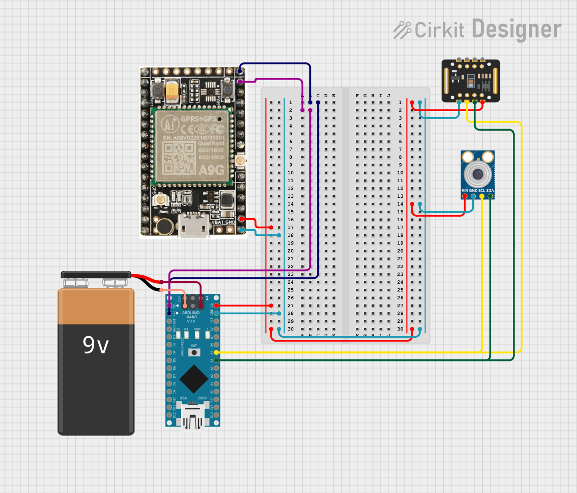
This document provides a detailed overview of a circuit that includes an Arduino Nano microcontroller, a MAX30102 sensor, an MLX90614 sensor, an A9G module, and a 9V battery. The circuit is designed to interface these components for data acquisition and processing. The Arduino Nano serves as the central microcontroller, managing communication between the sensors and the A9G module.
Component List
Arduino Nano
- Description: A small, complete, and breadboard-friendly board based on the ATmega328P.
- Pins: D1/TX, D0/RX, RESET, GND, D2, D3, D4, D5, D6, D7, D8, D9, D10, D11/MOSI, D12/MISO, VIN, 5V, A7, A6, A5, A4, A3, A2, A1, A0, AREF, 3V3, D13/SCK
MAX30102
- Description: A pulse oximeter and heart-rate sensor module.
- Pins: VIN, SDA, SCL, GND, RD, IRD, INT
MLX90614
- Description: An infrared thermometer for non-contact temperature measurements.
- Pins: SDA, SCL, GND, VIN
A9G
- Description: A GPS/GPRS module for location tracking and data communication.
- Pins: Data Pin 1, Data Pin 2, VCC, GND
9V Battery
- Description: A standard 9V battery for powering the circuit.
- Pins: +, -
Wiring Details
Arduino Nano
- D0/RX connected to A9G Data Pin 1
- D1/TX connected to A9G Data Pin 2
- VIN connected to MAX30102 VIN, MLX90614 VIN, A9G VCC
- GND connected to MAX30102 GND, MLX90614 GND, A9G GND, 9V Battery -
- A4 connected to MAX30102 SDA, MLX90614 SDA
- A5 connected to MAX30102 SCL, MLX90614 SCL
- 5V connected to 9V Battery +
MAX30102
- VIN connected to Arduino Nano VIN
- GND connected to Arduino Nano GND
- SDA connected to Arduino Nano A4
- SCL connected to Arduino Nano A5
MLX90614
- VIN connected to Arduino Nano VIN
- GND connected to Arduino Nano GND
- SDA connected to Arduino Nano A4
- SCL connected to Arduino Nano A5
A9G
- Data Pin 1 connected to Arduino Nano D0/RX
- Data Pin 2 connected to Arduino Nano D1/TX
- VCC connected to Arduino Nano VIN
- GND connected to Arduino Nano GND
9V Battery
- + connected to Arduino Nano 5V
- - connected to Arduino Nano GND
Documented Code
Arduino Nano Code (sketch.ino)
void setup() {
  // put your setup code here, to run once:

}

void loop() {
  // put your main code here, to run repeatedly:

}
Additional Documentation (documentation.txt)
This document provides a comprehensive overview of the circuit, including the components used, their connections, and the code running on the Arduino Nano. This should serve as a useful reference for understanding and replicating the circuit.