
Raspberry Pi 5-Based Multifunctional Robotic Controller with RFID and Audio Output
View and Edit Project In Cirkit Designer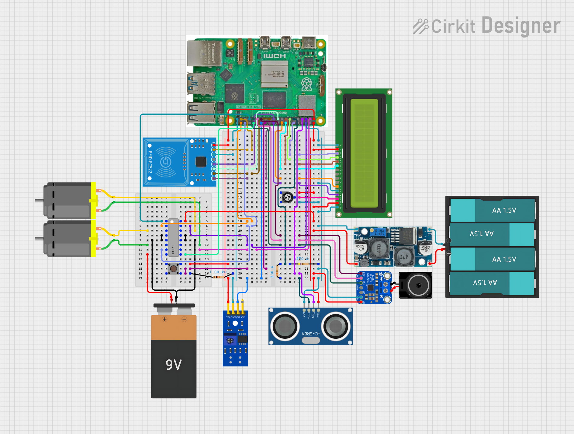
Circuit Documentation
Summary
This circuit integrates a variety of components including a Raspberry Pi 5, sensors (RFID-RC522, HC-SR04 Ultrasonic Sensor, KY-033 Line Tracking Sensor), an LCD Display (16x2), a motor driver (L293D), voltage regulation (XL6009 Voltage Regulator), audio output (Adafruit MAX98357A with Loudspeaker), and basic components like resistors, a trimmer potentiometer, a pushbutton, and power sources (Battery AAx4 6V and Battery 9V). The Raspberry Pi 5 serves as the central processing unit, interfacing with the sensors, controlling the LCD display, driving the motors through the L293D, and managing audio output through the Adafruit MAX98357A. The circuit is designed to perform tasks that require sensor input, visual feedback, motion control, and audio output.
Component List
Raspberry Pi 5
- A microcomputer with multiple GPIO pins used for interfacing with various components such as sensors, displays, and motor drivers.
KY-033 Line Tracking Sensor
- A sensor used to detect and follow a line on the ground.
HC-SR04 Ultrasonic Sensor
- A sensor that measures distance using ultrasonic waves.
RFID-RC522
- An RFID reader/writer for contactless communication using radio frequency.
LCD Display 16x2
- A display with 2 lines of 16 characters each, used for visual output.
Resistor (470 Ohms)
- A passive component used to limit current or divide voltage.
Trimmer Potentiometer (10k Ohms)
- A variable resistor used to adjust levels such as contrast on an LCD.
XL6009 Voltage Regulator
- A DC-DC converter used to step up or step down voltage levels.
DC Motor
- An electric motor that converts electrical energy into mechanical motion.
Battery AAx4 6V
- A power source providing 6V from four AA batteries.
L293D
- A motor driver IC capable of driving two DC motors.
Battery 9V
- A standard 9V battery used as a power source.
Adafruit MAX98357A
- An I2S Class-D Mono Amplifier used for audio output.
Loudspeaker
- An electroacoustic transducer used to produce sound.
Pushbutton
- A momentary switch used to trigger actions.
Resistor (330 Ohms)
- Another passive component used to limit current or divide voltage.
Resistor (1k Ohms)
- Another passive component with a higher resistance value.
Wiring Details
Raspberry Pi 5
- GPIO 26 connected to RFID-RC522 RST
- GPIO 18 connected to LCD Display DB7
- GPIO 27 connected to LCD Display DB6
- GPIO 9 connected to RFID-RC522 MISO
- GPIO 22 connected to LCD Display DB5
- GPIO 10 connected to RFID-RC522 MOSI
- GPIO 23 connected to LCD Display DB4
- GPIO 11 connected to RFID-RC522 SCK
- GPIO 8 connected to RFID-RC522 SDA
- GPIO 24 connected to LCD Display E
- GPIO 25 connected to LCD Display RS
- 5V connected to multiple components for power
- GND connected to multiple components for ground
- GPIO 20 connected to L293D Input 1
- GPIO 16 connected to L293D Input 2
- GPIO 0 connected to Adafruit MAX98357A LRCLK
- GPIO 5 connected to Adafruit MAX98357A BCLK
- GPIO 3 connected to L293D Input 4
- GPIO 6 connected to Adafruit MAX98357A DIN
- GPIO 2 connected to L293D Input 3
- GPIO 17 connected to a 470 Ohm resistor
- GPIO 7 connected to a pushbutton and a 1k Ohm resistor
- GPIO 4 connected to HC-SR04 Ultrasonic Sensor TRIG
- GPIO 1 connected to KY-033 Line Tracking Sensor D0
- GPIO 13 connected to L293D Enable 1,2
- GPIO 12 connected to L293D Enable 3,4
- 3.3v connected to the pushbutton and RFID-RC522 3.3V
KY-033 Line Tracking Sensor
- D0 connected to Raspberry Pi GPIO 1
- VCC connected to 3.3V
- GND connected to ground
HC-SR04 Ultrasonic Sensor
- VCC connected to 5V
- TRIG connected to Raspberry Pi GPIO 4
- ECHO connected to a 330 Ohm resistor
- GND connected to ground
RFID-RC522
- SDA connected to Raspberry Pi GPIO 8
- SCK connected to Raspberry Pi GPIO 11
- MOSI connected to Raspberry Pi GPIO 10
- MISO connected to Raspberry Pi GPIO 9
- IRQ not connected
- GND connected to ground
- RST connected to Raspberry Pi GPIO 26
- 3.3V connected to 3.3V
LCD Display 16x2
- DB7 connected to Raspberry Pi GPIO 18
- DB6 connected to Raspberry Pi GPIO 27
- DB5 connected to Raspberry Pi GPIO 22
- DB4 connected to Raspberry Pi GPIO 23
- E connected to Raspberry Pi GPIO 24
- RS connected to Raspberry Pi GPIO 25
- LEDA connected to 5V
- LEDK, RW, VSS connected to ground
- VO connected to the wiper of the trimmer potentiometer
Resistor (470 Ohms)
- One side connected to Raspberry Pi GPIO 17
Trimmer Potentiometer (10k Ohms)
- Leg1 connected to 5V
- Wiper connected to LCD Display VO
- Leg2 connected to a 470 Ohm resistor and ground
XL6009 Voltage Regulator
- OUT + connected to 5V
- OUT - connected to ground
- IN + connected to Battery AAx4 6V VCC
- IN - connected to Battery AAx4 6V GND
DC Motor
- One motor's pin 1 connected to L293D Output 2
- The same motor's pin 2 connected to L293D Output 1
- Another motor's pin 1 connected to L293D Output 3
- The other motor's pin 2 connected to L293D Output 4
Battery AAx4 6V
- VCC connected to XL6009 IN +
- GND connected to XL6009 IN -
L293D
- Enable 1,2 connected to Raspberry Pi GPIO 13
- Input 1 connected to Raspberry Pi GPIO 20
- Output 1 connected to one DC Motor pin 2
- Output 2 connected to the same DC Motor pin 1
- VCC1 connected to 5V
- VCC2 connected to Battery 9V VCC
- Input 2 connected to Raspberry Pi GPIO 16
- Input 3 connected to Raspberry Pi GPIO 2
- Input 4 connected to Raspberry Pi GPIO 3
- Output 3 connected to another DC Motor pin 1
- Output 4 connected to the same DC Motor pin 2
- Enable 3,4 connected to Raspberry Pi GPIO 12
- GND connected to Battery 9V GND
Battery 9V
- VCC connected to L293D VCC2
- GND connected to L293D GND
Adafruit MAX98357A
- VIN connected to 5V
- GND connected to ground
- LRCLK connected to Raspberry Pi GPIO 0
- GAIN not connected
- DIN connected to Raspberry Pi GPIO 6
- BCLK connected to Raspberry Pi GPIO 5
- VO+ connected to Loudspeaker pin 2
- VO- connected to Loudspeaker pin 1
Loudspeaker
- Pin 1 connected to Adafruit MAX98357A VO-
- Pin 2 connected to Adafruit MAX98357A VO+
Pushbutton
- Pin 1 (in) connected to 3.3V
- Pin 3 (out) connected to a 1k Ohm resistor
Resistor (330 Ohms)
- One side connected to HC-SR04 Ultrasonic Sensor ECHO
Resistor (1k Ohms)
- One side connected to Pushbutton Pin 3 (out)
- The other side connected to ground
Documented Code
No code was provided for the microcontrollers in the circuit. Therefore, this section is left blank until the relevant code is supplied.