Cirkit Designer
Your all-in-one circuit design IDE
Home /
Project Documentation
Raspberry Pi Pico W Wi-Fi Controlled Dual DC Motor Driver
Circuit Documentation
Summary
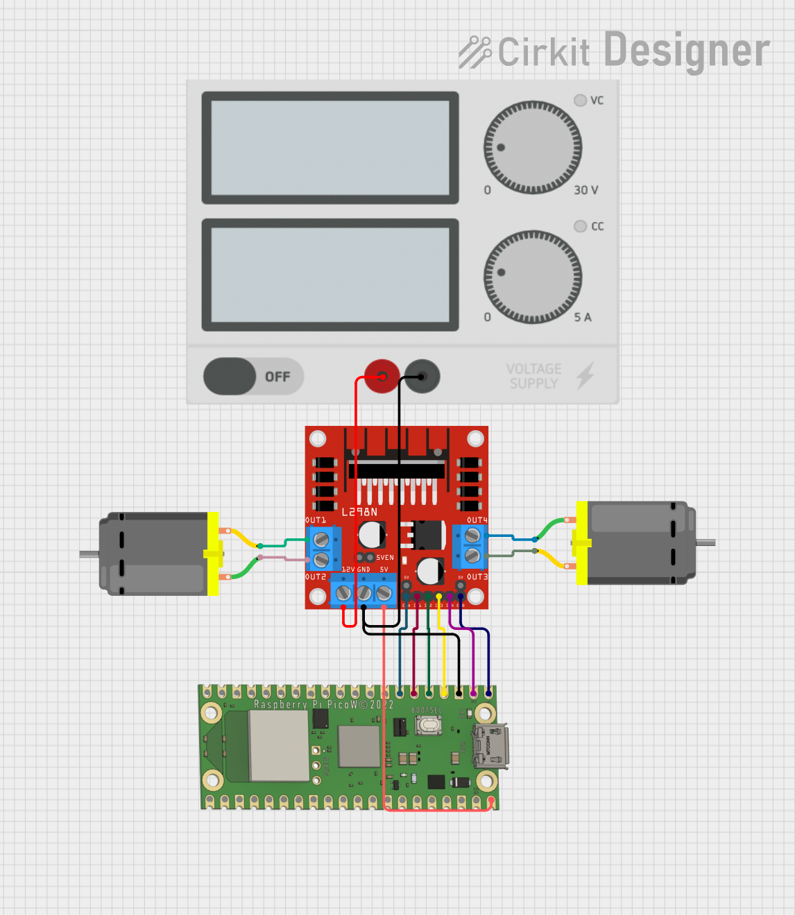
This circuit involves a Raspberry Pi Pico W microcontroller, an L298N DC motor driver, two DC motors, and a power supply. The Raspberry Pi Pico W controls the L298N motor driver, which in turn drives the two DC motors. The power supply provides the necessary voltage to the motor driver.
Component List
Raspberry Pi Pico W
- Description: A microcontroller board with Wi-Fi capabilities.
- Pins: VBUS, VSYS, GP16, GP17, GND, GP18, GP19, GP20, GP21, GP22, RUN, GP26, GP27, GP28, ADC_VREF, 3V3 OUT, 3V3_EN, GP0, GP1, GP2, GP3, GP4, GP5, GP6, GP7, GP15, GP14, GP13, GP12, GP11, GP10, GP9, GP8
DC Motor (Motor 1)
- Description: A simple DC motor.
- Pins: pin 1, pin 2
DC Motor (Motor 2)
- Description: A simple DC motor.
- Pins: pin 1, pin 2
L298N DC Motor Driver
- Description: A dual H-Bridge motor driver.
- Pins: OUT1, OUT2, 12V, GND, 5V, OUT3, OUT4, 5V-ENA-JMP-I, 5V-ENA-JMP-O, +5V-J1, +5V-J2, ENA, IN1, IN2, IN3, IN4, ENB
Power Supply
- Description: Provides power to the circuit.
- Pins: +, -
Wiring Details
Raspberry Pi Pico W
- VBUS is connected to 5V on the L298N DC motor driver.
- GP0 is connected to ENB on the L298N DC motor driver.
- GP1 is connected to IN4 on the L298N DC motor driver.
- GND is connected to - on the Power Supply and GND on the L298N DC motor driver.
- GP2 is connected to IN3 on the L298N DC motor driver.
- GP3 is connected to IN2 on the L298N DC motor driver.
- GP4 is connected to IN1 on the L298N DC motor driver.
- GP5 is connected to ENA on the L298N DC motor driver.
DC Motor (Motor 1)
- pin 2 is connected to OUT1 on the L298N DC motor driver.
- pin 1 is connected to OUT2 on the L298N DC motor driver.
DC Motor (Motor 2)
- pin 2 is connected to OUT3 on the L298N DC motor driver.
- pin 1 is connected to OUT4 on the L298N DC motor driver.
L298N DC Motor Driver
- 5V is connected to VBUS on the Raspberry Pi Pico W.
- ENB is connected to GP0 on the Raspberry Pi Pico W.
- IN4 is connected to GP1 on the Raspberry Pi Pico W.
- GND is connected to GND on the Raspberry Pi Pico W and - on the Power Supply.
- IN3 is connected to GP2 on the Raspberry Pi Pico W.
- IN2 is connected to GP3 on the Raspberry Pi Pico W.
- IN1 is connected to GP4 on the Raspberry Pi Pico W.
- ENA is connected to GP5 on the Raspberry Pi Pico W.
- OUT1 is connected to pin 2 on DC Motor 1.
- OUT2 is connected to pin 1 on DC Motor 1.
- OUT3 is connected to pin 2 on DC Motor 2.
- OUT4 is connected to pin 1 on DC Motor 2.
- 12V is connected to + on the Power Supply.
Power Supply
- - is connected to GND on the Raspberry Pi Pico W and GND on the L298N DC motor driver.
- + is connected to 12V on the L298N DC motor driver.
Code
No code is provided for this circuit.