
Arduino-Controlled Solar-Assisted Dual-Motor System with LCD Interface
View and Edit Project In Cirkit Designer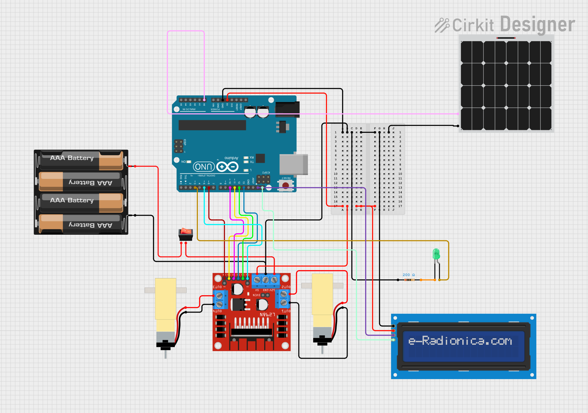
Circuit Documentation
Summary
This circuit is designed to control two hobby gearmotors using an L298N DC motor driver, with an Arduino UNO as the central microcontroller. The circuit includes a 4 x AAA battery mount for power, a solar panel for additional power input, and a rocker switch to control the power flow. An LCD screen is interfaced with the Arduino for display purposes. A green LED with a resistor is also included, likely for status indication. The solar panel is connected to an analog input on the Arduino for potential solar power monitoring.
Component List
4 x AAA Battery Mount
- Description: A battery holder for four AAA batteries, providing power to the circuit.
Arduino UNO
- Description: A microcontroller board based on the ATmega328P, used as the main controller for the circuit.
L298N DC Motor Driver
- Description: A motor driver module capable of driving two DC motors or one stepper motor.
Rocker Switch
- Description: A switch used to control the connection between the battery mount and the rest of the circuit.
Hobby Gearmotor with 48:1 Gearbox (x2)
- Description: DC motors with gear reduction, used for driving mechanical parts.
LED: Two Pin (green)
- Description: A green LED used for status indication or visual feedback.
Resistor
- Description: A 200 Ohm resistor, likely used to limit current to the LED.
LCD Screen 16x2 I2C
- Description: An alphanumeric LCD display module with I2C interface for displaying data.
Solar Panel
- Description: A photovoltaic panel used to convert solar energy into electrical power.
Wiring Details
4 x AAA Battery Mount
- "+" connected to the rocker switch input.
- "-" connected to the common ground net.
Arduino UNO
- "GND" connected to the common ground net.
- "5V" connected to the 5V net, providing power to the L298N motor driver and the LCD screen.
- "A0" connected to the "+" of the solar panel for potential solar power monitoring.
- "SCL" and "SDA" connected to the corresponding pins on the LCD screen for I2C communication.
- "D13", "D12", "D11", "D10", "D6", "D5", "D3" connected to the L298N motor driver for motor control and to the anode of the LED.
L298N DC Motor Driver
- "GND" connected to the common ground net.
- "5V" connected to the 5V net.
- "12V" connected to the rocker switch output.
- "ENA", "ENB", "IN1", "IN2", "IN3", "IN4" connected to the corresponding digital pins on the Arduino UNO for motor control.
- "OUT1", "OUT2" connected to one of the hobby gearmotors.
- "OUT3", "OUT4" connected to the other hobby gearmotor.
Rocker Switch
- "input" connected to the "+" of the 4 x AAA battery mount.
- "output" connected to the "12V" of the L298N motor driver.
Hobby Gearmotor with 48:1 Gearbox
- Two instances, each connected to a pair of outputs from the L298N motor driver.
LED: Two Pin (green)
- "anode" connected to "D3" on the Arduino UNO.
- "cathode" connected to one end of the resistor.
Resistor
- One end connected to the "cathode" of the LED.
- The other end connected to the common ground net.
LCD Screen 16x2 I2C
- "SCL" and "SDA" connected to the corresponding pins on the Arduino UNO for I2C communication.
- "VCC" connected to the 5V net.
- "GND" connected to the common ground net.
Solar Panel
- "+" connected to "A0" on the Arduino UNO for potential solar power monitoring.
- "-" connected to the common ground net.
Documented Code
// Code for Arduino UNO
// Filename: sketch.ino

// The code for the Arduino UNO is not provided in the input.
// Please insert the appropriate code here.
Please note that the actual code for the Arduino UNO was not provided in the input. The code should be inserted where indicated in the documented code section.