
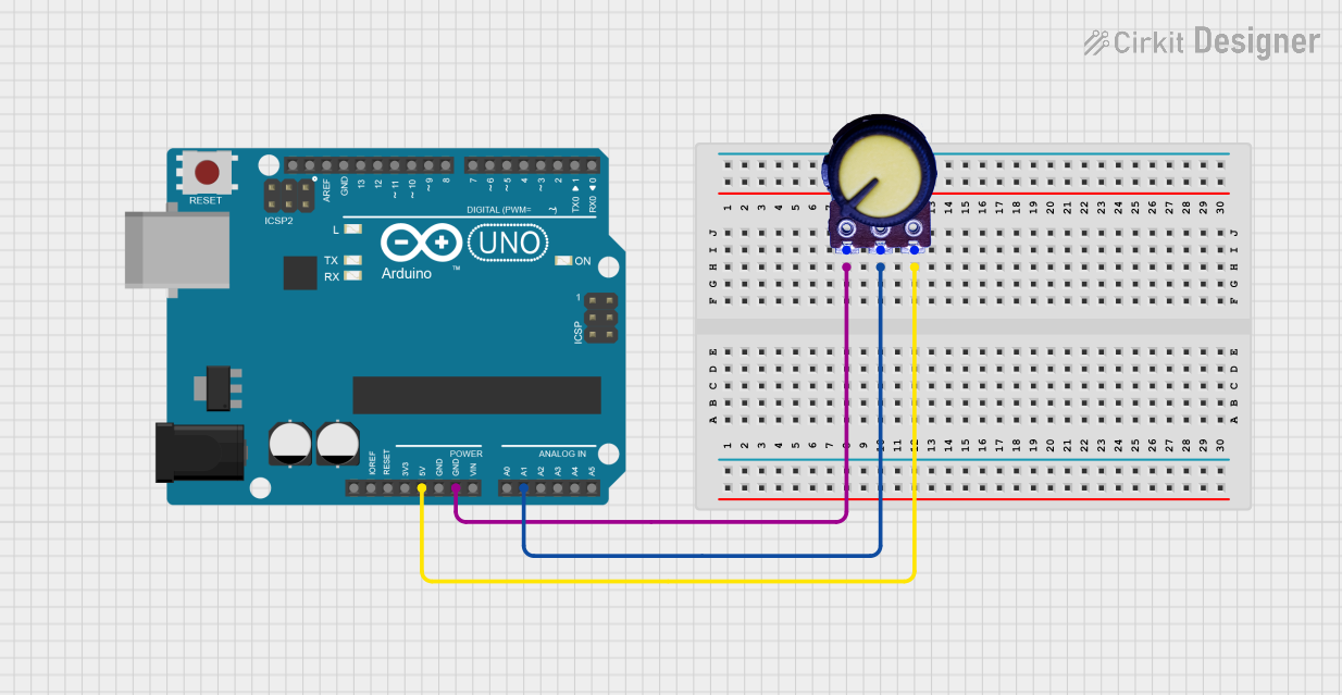
Circuit Documentation
Summary
This circuit consists of an Arduino UNO microcontroller and a potentiometer. The potentiometer is connected to the Arduino UNO to provide an analog input that can be read by the microcontroller. The Arduino UNO is programmed to read the potentiometer's output and can be further developed to perform various tasks based on the input.
Component List
Arduino UNO
- Description: A microcontroller board based on the ATmega328P.
- Pins: UNUSED, IOREF, Reset, 3.3V, 5V, GND, Vin, A0, A1, A2, A3, A4, A5, SCL, SDA, AREF, D13, D12, D11, D10, D9, D8, D7, D6, D5, D4, D3, D2, D1, D0
Potentiometer
- Description: A three-terminal resistor with a sliding or rotating contact that forms an adjustable voltage divider.
- Pins: GND, Output, VCC
Wiring Details
Arduino UNO
- 5V: Connected to VCC of the Potentiometer
- GND: Connected to GND of the Potentiometer
- A1: Connected to Output of the Potentiometer
Potentiometer
- VCC: Connected to 5V of the Arduino UNO
- GND: Connected to GND of the Arduino UNO
- Output: Connected to A1 of the Arduino UNO
Documented Code
Arduino UNO Code (sketch.ino)
void setup() {
  // put your setup code here, to run once:

}

void loop() {
  // put your main code here, to run repeatedly:

}
Additional Documentation (documentation.txt)
This documentation provides a comprehensive overview of the circuit, including a summary, detailed component list, wiring details, and the code used in the Arduino UNO.