
555 Timer-Based LED Flasher Circuit with Adjustable Flash Rate
View and Edit Project In Cirkit Designer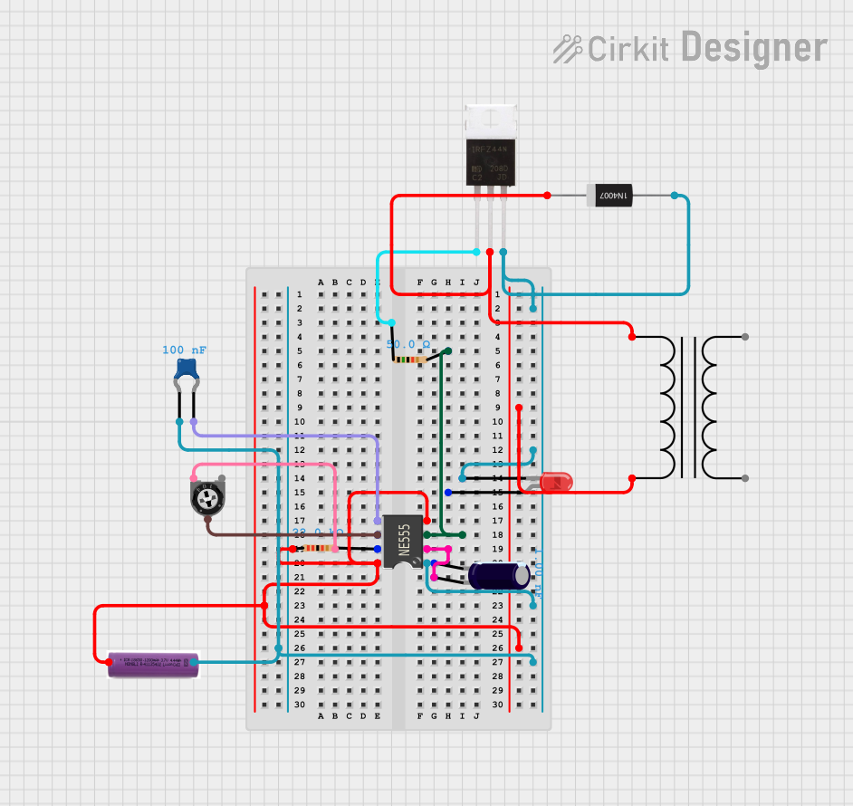
Circuit Documentation
Summary
This document provides a detailed overview of a circuit that incorporates a 555 Timer IC as the central component. The circuit is designed to generate an output signal with characteristics determined by the connected passive components. The circuit includes a power supply, timing elements, a control voltage capacitor, an LED indicator, a MOSFET, and a rectifier diode for protection. The 555 Timer IC is configured with external resistors and capacitors to set its timing parameters. The circuit does not include any microcontroller code.
Component List
555 Timer IC
- Description: A highly stable device for generating accurate time delays or oscillation.
- Pins: VCC+, Dis, Th, CV, Rst, Out, Trig, GND
Electrolytic Capacitor
- Description: A polarized capacitor with a capacitance of 1 nF.
- Properties: Capacitance: 1e-9 Farads
Resistor (22 kΩ)
- Description: A resistor with a resistance of 22 kΩ.
- Properties: Resistance: 22000 Ohms
Trimmer Potentiometer
- Description: An adjustable resistor with a maximum resistance of 100 kΩ.
- Properties: Resistance: 100000 Ohms
3.7v Battery
- Description: A power source with a voltage of 3.7 volts.
LED: Two Pin (Red)
- Description: A red light-emitting diode.
Ceramic Capacitor
- Description: A non-polarized capacitor with a capacitance of 100 pF.
- Properties: Capacitance: 0.0000001 Farads
IRFZ44N
- Description: A power MOSFET used for switching heavy loads.
Resistor (50 Ω)
- Description: A resistor with a resistance of 50 Ω.
- Properties: Resistance: 50 Ohms
1N4007 Rectifier Diode
- Description: A diode used for rectification and protection against reverse polarity.
Power Transformer
- Description: A transformer used to step up or step down the voltage.
Wiring Details
555 Timer IC
- VCC+: Connected to the positive terminal of the 3.7v battery and one terminal of the 22 kΩ resistor.
- Dis: Connected to one terminal of the 22 kΩ resistor and leg2 of the Trimmer Potentiometer.
- Th: Connected to the wiper of the Trimmer Potentiometer.
- CV: Connected to one terminal of the Ceramic Capacitor.
- Rst: Connected to the positive terminal of the 3.7v battery.
- Out: Connected to one terminal of the 50 Ω resistor.
- Trig: Connected to the positive terminal of the Electrolytic Capacitor.
- GND: Connected to the cathode of the LED, Anode of the 1N4007 Rectifier Diode, Source of the IRFZ44N, pin0 of the Ceramic Capacitor, and the negative terminal of the 3.7v battery.
Electrolytic Capacitor
- +: Connected to the Trig pin of the 555 Timer IC.
- -: Not connected in the provided net list.
Resistor (22 kΩ)
- pin1: Connected to the VCC+ pin of the 555 Timer IC.
- pin2: Connected to the Dis pin of the 555 Timer IC and leg2 of the Trimmer Potentiometer.
Trimmer Potentiometer
- leg1: Not connected in the provided net list.
- wiper: Connected to the Th pin of the 555 Timer IC.
- leg2: Connected to the Dis pin of the 555 Timer IC and pin2 of the 22 kΩ resistor.
3.7v Battery
- +: Connected to the VCC+ and Rst pins of the 555 Timer IC.
- -: Connected to the GND pin of the 555 Timer IC.
LED: Two Pin (Red)
- cathode: Connected to the GND pin of the 555 Timer IC.
- anode: Not connected in the provided net list.
Ceramic Capacitor
- pin0: Connected to the GND pin of the 555 Timer IC.
- pin1: Connected to the CV pin of the 555 Timer IC.
IRFZ44N
- Gate: Connected to one terminal of the 50 Ω resistor.
- Drain: Connected to the Cathode of the 1N4007 Rectifier Diode.
- Source: Connected to the GND pin of the 555 Timer IC.
Resistor (50 Ω)
- pin1: Connected to the Gate of the IRFZ44N.
- pin2: Connected to the Out pin of the 555 Timer IC.
1N4007 Rectifier Diode
- Cathode: Connected to the Drain of the IRFZ44N and 1 - Primary of the Power Transformer.
- Anode: Connected to the GND pin of the 555 Timer IC.
Power Transformer
- 1 - Primary: Connected to the Cathode of the 1N4007 Rectifier Diode.
- 2 - Primary: Connected to the VCC+ pin of the 555 Timer IC.
- 3 - Secondary: Not connected in the provided net list.
- 4 - Secondary: Not connected in the provided net list.
Documented Code
No code has been provided for any microcontrollers in the circuit. Therefore, this section is not applicable to the current documentation.