Arduino Mega 2560 and ESP8266 Nodemcu Based Climate Monitoring and Water Level Control System
Circuit Documentation
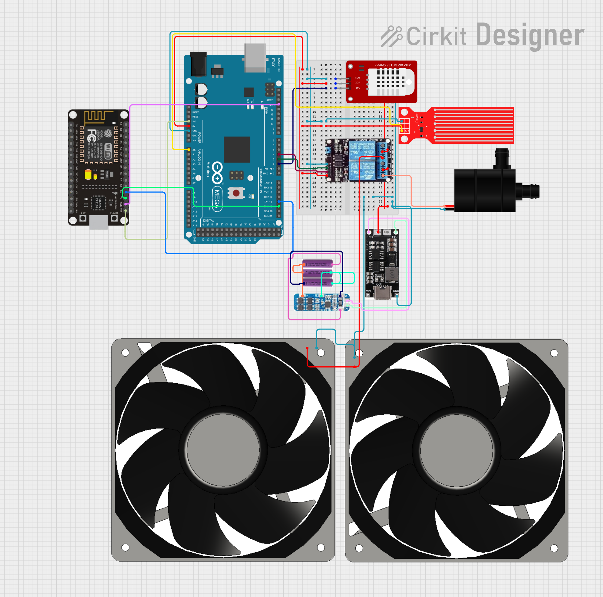
Summary
This circuit is designed to monitor environmental conditions and control a water pump and fans based on temperature and water level readings. It uses an Arduino Mega 2560 as the main microcontroller to read data from a DHT22 temperature and humidity sensor and a water level sensor. The Arduino controls a 2-channel relay module, which in turn controls the power to a water pump and two 12V fans. The system also includes an ESP8266 NodeMCU for potential wireless communication capabilities. Power management is handled by a combination of 3.7V batteries, a lithium-ion charger, and a Battery Management System (BMS).
Component List
- Arduino Mega 2560: A microcontroller board based on the ATmega2560, with numerous digital and analog I/O pins.
- DHT22: A sensor for measuring temperature and humidity.
- Water Level Sensor: A sensor used to detect the level of water.
- 2-Channel Relay Module: An electrically operated switch that allows the Arduino to control higher power devices like the water pump and fans.
- Water Pump: A device used to move water from one place to another.
- 120mm 12V Fans (x2): Fans used for cooling or ventilation purposes.
- 3.7V Batteries (x3): Batteries used to provide power to the circuit.
- 18650 Lithium-Ion Charger: A charging module for lithium-ion batteries.
- Battery Management System (BMS): A system that manages a rechargeable battery by protecting the battery from operating outside its safe operating area.
- ESP8266 NodeMCU: A low-cost Wi-Fi microchip with full TCP/IP stack and microcontroller capability.
Wiring Details
Arduino Mega 2560
- GND: Connected to the ground pins of the DHT22, Water Level Sensor, 2-Channel Relay, and ESP8266 NodeMCU.
- 5V: Powers the DHT22, Water Level Sensor, and 2-Channel Relay.
- 3V3: Powers the ESP8266 NodeMCU.
- D2 PWM: Connected to the data pin of the DHT22.
- A0: Reads the signal from the Water Level Sensor.
- D19/RX1: Receives data from the ESP8266 NodeMCU TX pin.
- D18/TX1: Transmits data to the ESP8266 NodeMCU RX pin.
- D3 PWM: Controls the IN1 pin on the 2-Channel Relay to control the water pump.
- D4 PWM: Controls the IN2 pin on the 2-Channel Relay to control the fans.
DHT22
- GND: Ground connection.
- VCC: Powered by the 5V output from the Arduino Mega 2560.
- DAT: Sends temperature and humidity data to the Arduino Mega 2560 D2 PWM pin.
Water Level Sensor
- GND: Ground connection.
- VCC: Powered by the 5V output from the Arduino Mega 2560.
- SIG: Sends water level data to the Arduino Mega 2560 A0 pin.
2-Channel Relay Module
- GND: Ground connection.
- VCC: Powered by the 5V output from the Arduino Mega 2560.
- IN1: Controlled by the Arduino Mega 2560 D3 PWM pin to activate/deactivate the water pump.
- IN2: Controlled by the Arduino Mega 2560 D4 PWM pin to activate/deactivate the fans.
- COM: Connected to the OUT pin of the 18650 Lithium-Ion Charger.
- NO: Normally open contact used to control the water pump and fans.
Water Pump
- GND: Ground connection.
- VCC: Powered through the 2-Channel Relay NO contact.
120mm 12V Fans
- GND: Ground connection.
- 12V+: Powered through the 2-Channel Relay NO contact.
3.7V Batteries
- +: Positive terminal connected in series through the BMS.
- -: Negative terminal connected in series through the BMS.
18650 Lithium-Ion Charger
- GND: Ground connection.
- OUT: Connected to the COM pin of the 2-Channel Relay.
- BAT IN: Connected to the P+ pin of the BMS.
- BAT GND: Connected to the P- pin of the BMS.
Battery Management System (BMS)
- B+, B2, B1, B-: Connected to the respective battery terminals in series.
- P+: Connected to the BAT IN pin of the 18650 Lithium-Ion Charger.
- P-: Connected to the BAT GND pin of the 18650 Lithium-Ion Charger.
ESP8266 NodeMCU
- 3V3: Powered by the 3.3V output from the Arduino Mega 2560.
- GND: Ground connection.
- RX: Receives data from the Arduino Mega 2560 D18/TX1 pin.
- TX: Transmits data to the Arduino Mega 2560 D19/RX1 pin.
Documented Code
#include <DHT.h>
#include <Wire.h>

#define DHTPIN 2
#define DHTTYPE DHT22
#define WATER_LEVEL_PIN A0
#define RELAY_PUMP_PIN 3
#define RELAY_FAN_PIN 4

DHT dht(DHTPIN, DHTTYPE);

void setup() {
  Serial.begin(9600);
  Serial1.begin(115200); // Communication with ESP32
  dht.begin();

  pinMode(WATER_LEVEL_PIN, INPUT);
  pinMode(RELAY_PUMP_PIN, OUTPUT);
  pinMode(RELAY_FAN_PIN, OUTPUT);

  digitalWrite(RELAY_PUMP_PIN, LOW);
  digitalWrite(RELAY_FAN_PIN, LOW);
}

void loop() {
  float temperature = dht.readTemperature();
  float humidity = dht.readHumidity();
  int waterLevel = analogRead(WATER_LEVEL_PIN);

  // Send data to ESP32
  Serial1.print("Temperature: ");
  Serial1.print(temperature);
  Serial1.print(" C, Humidity: ");
  Serial1.print(humidity);
  Serial1.print(" %, Water Level: ");
  Serial1.print(waterLevel);
  Serial1.println(" mm");

  // Check if the temperature is below 15 degrees Celsius
  if (temperature < 15.0 && waterLevel > 3) {
    digitalWrite(RELAY_PUMP_PIN, HIGH); // Activate water pump
    digitalWrite(RELAY_FAN_PIN, HIGH);  // Activate fans
  } else {
    digitalWrite(RELAY_PUMP_PIN, LOW);  // Deactivate water pump
    digitalWrite(RELAY_FAN_PIN, LOW);   // Deactivate fans
  }

  delay(2000); // Wait for 2 seconds before the next reading
}
The code is written for the Arduino Mega 2560 and is responsible for initializing the DHT22 sensor, setting up the communication with the ESP8266 NodeMCU, reading sensor data, and controlling the relay module based on the temperature and water level conditions. It sends sensor data to the ESP8266 NodeMCU for potential wireless transmission.