
Arduino UNO Based Ultrasonic Distance Sensor with Alert System
View and Edit Project In Cirkit Designer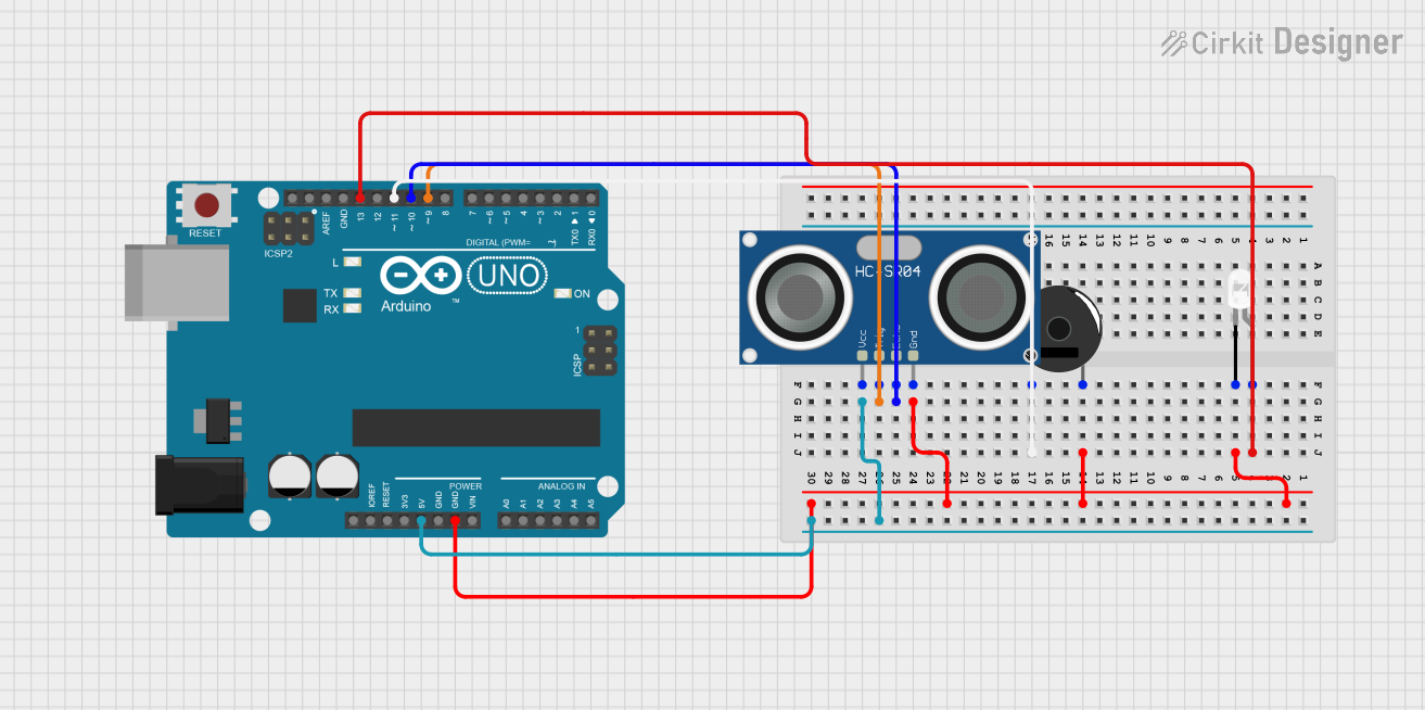
Circuit Documentation
Summary
This circuit is designed to utilize an Arduino UNO microcontroller to interface with an HC-SR04 Ultrasonic Sensor, a Piezo Buzzer, and an LED. The primary function of this circuit is to measure distance using the ultrasonic sensor and provide an alert through the buzzer and LED when an object is within a predefined safety distance. The Arduino UNO controls the sensor to emit ultrasonic waves and listens for the echo to calculate the distance to an object. If the measured distance is within the safety threshold, the buzzer is activated, and the LED is turned on to signal proximity.
Component List
Arduino UNO
- Description: A microcontroller board based on the ATmega328P.
- Purpose: Acts as the central processing unit of the circuit, controlling the sensor, buzzer, and LED.
HC-SR04 Ultrasonic Sensor
- Description: An ultrasonic distance sensor capable of measuring distances by emitting and receiving ultrasonic waves.
- Purpose: Measures the distance to objects in front of the sensor.
Piezo Buzzer
- Description: An electronic device that emits sound when an electric signal is applied.
- Purpose: Provides an audible alert when an object is within the safety distance.
LED: Two Pin (white)
- Description: A basic light-emitting diode that emits white light.
- Purpose: Provides a visual alert when an object is within the safety distance.
Wiring Details
Arduino UNO
- 5V: Powers the HC-SR04 Ultrasonic Sensor.
- GND: Common ground for the LED, Piezo Buzzer, HC-SR04 Ultrasonic Sensor, and Arduino UNO.
- D13: Connected to the anode of the LED.
- D11: Connected to pin 1 of the Piezo Buzzer.
- D10: Connected to the ECHO pin of the HC-SR04 Ultrasonic Sensor.
- D9: Connected to the TRIG pin of the HC-SR04 Ultrasonic Sensor.
HC-SR04 Ultrasonic Sensor
- VCC: Connected to the 5V output of the Arduino UNO.
- TRIG: Connected to pin D9 of the Arduino UNO.
- ECHO: Connected to pin D10 of the Arduino UNO.
- GND: Connected to the common ground.
Piezo Buzzer
- pin 1: Connected to pin D11 of the Arduino UNO.
- pin 2: Connected to the common ground.
LED: Two Pin (white)
- anode: Connected to pin D13 of the Arduino UNO.
- cathode: Connected to the common ground.
Documented Code
// defines pins numbers
const int trigPin = 9;
const int echoPin = 10;
const int buzzer = 11;
const int ledPin = 13;
// defines variables
long duration;
int distance;
int safetyDistance;

void setup() {
  pinMode(trigPin, OUTPUT); // Sets the trigPin as an Output
  pinMode(echoPin, INPUT); // Sets the echoPin as an Input
  pinMode(buzzer, OUTPUT);
  pinMode(ledPin, OUTPUT);
  Serial.begin(9600); // Starts the serial communication
}

void loop() {
  // Clears the trigPin
  digitalWrite(trigPin, LOW);
  delayMicroseconds(2);
  // Sets the trigPin on HIGH state for 10 micro seconds
  digitalWrite(trigPin, HIGH);
  delayMicroseconds(10);
  digitalWrite(trigPin, LOW);
  // Reads the echoPin, returns the sound wave travel time in microseconds
  duration = pulseIn(echoPin, HIGH);
  // Calculating the distance
  distance= duration*0.034/2;
  safetyDistance = distance;
  if (safetyDistance <= 5){
    digitalWrite(buzzer, HIGH);
    digitalWrite(ledPin, HIGH);
  }
  else{
    digitalWrite(buzzer, LOW);
    digitalWrite(ledPin, LOW);
  }
  // Prints the distance on the Serial Monitor
  Serial.print("Distance: ");
  Serial.println(distance);
}
This code is designed to run on the Arduino UNO microcontroller. It initializes the pins connected to the ultrasonic sensor, buzzer, and LED. In the main loop, it triggers the ultrasonic sensor to send a pulse and listens for the echo to calculate the distance to an object. If the distance is less than or equal to 5 units (presumably centimeters), it activates the buzzer and turns on the LED as an alert. The distance is also printed to the serial monitor for debugging purposes.