
ESP8266 NodeMCU Controlled Lighting System with LDR and Adjustable Voltage
View and Edit Project In Cirkit Designer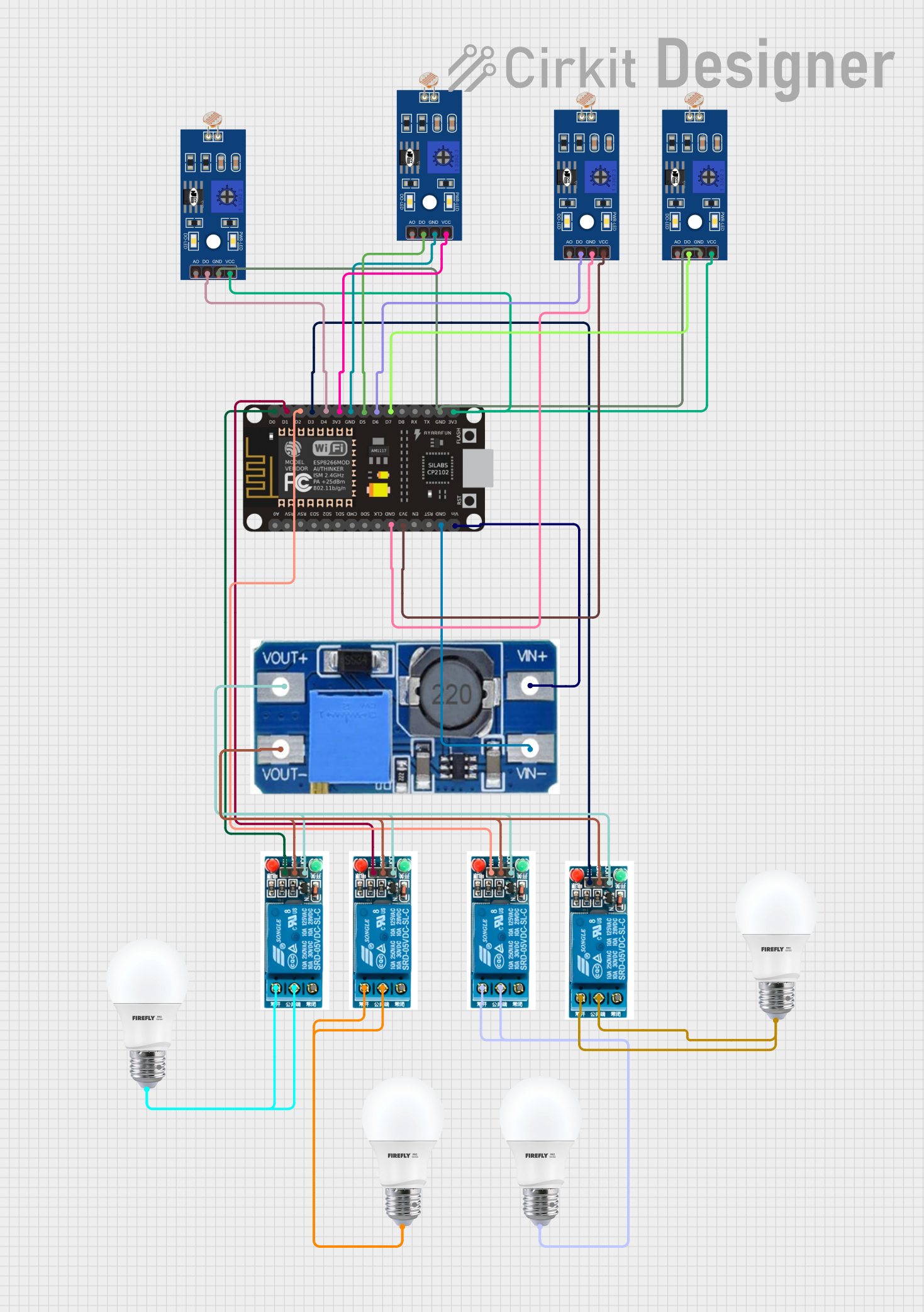
Circuit Documentation
Summary
The circuit is designed to control multiple bulbs using an ESP8266 NodeMCU microcontroller in conjunction with several 5V relays. Light-dependent resistors (LDRs) are used to provide input to the microcontroller, which then decides whether to activate the relays and turn the bulbs on or off. A Step Up Boost Power Converter is used to adjust the voltage levels appropriate for the relays.
Component List
ESP8266 NodeMCU
- Microcontroller with WiFi capability.
- It has multiple digital and analog pins, along with power and ground pins.
Step Up Boost Power Converter, Adjustable Voltage Regulator
- Used to step up the voltage to a level suitable for the relays.
- It has input and output voltage pins.
Bulbs
- Four bulbs are used as the output devices to be controlled by the relays.
LDR (Light-Dependent Resistor)
- Four LDRs are used to sense the ambient light level.
- They provide analog input to the microcontroller.
5V Relay
- Four relays are used to switch the bulbs on and off.
- Each relay has a Normally Open (NO), Common terminal (COM), Normally Closed (NC), Input (In), Ground (GND), and Voltage (VCC) pin.
Wiring Details
ESP8266 NodeMCU
- D0 connected to Relay In (Relay 1)
- D1 connected to Relay In (Relay 4)
- D2 connected to Relay In (Relay 3)
- D3 connected to Relay In (Relay 2)
- D4 connected to LDR D0 (LDR 4)
- D5 connected to LDR D0 (LDR 2)
- D6 connected to LDR D0 (LDR 1)
- D7 connected to LDR D0 (LDR 3)
- 3V3 connected to LDR VCC (LDRs 1, 2, 3, 4)
- GND connected to LDR GND (LDRs 1, 2, 3, 4), Relay GND (Relays 1, 2, 3, 4), and Power Converter VIN-
- VIN connected to Power Converter VIN+
Step Up Boost Power Converter, Adjustable Voltage Regulator
- VIN+ connected to ESP8266 NodeMCU VIN
- VIN- connected to ESP8266 NodeMCU GND
- VOUT+ connected to Relay VCC (Relays 1, 2, 3, 4)
- VOUT- connected to Relay GND (Relays 1, 2, 3, 4)
Bulbs
- Bulb 1 connected to Relay NO and COM (Relay 4)
- Bulb 2 connected to Relay NO and COM (Relay 3)
- Bulb 3 connected to Relay NO and COM (Relay 2)
- Bulb 4 connected to Relay NO and COM (Relay 1)
LDRs
- LDR 1 D0 connected to ESP8266 NodeMCU D6
- LDR 2 D0 connected to ESP8266 NodeMCU D5
- LDR 3 D0 connected to ESP8266 NodeMCU D7
- LDR 4 D0 connected to ESP8266 NodeMCU D4
- All LDRs VCC connected to ESP8266 NodeMCU 3V3
- All LDRs GND connected to ESP8266 NodeMCU GND
5V Relays
- Relay 1 In connected to ESP8266 NodeMCU D0
- Relay 2 In connected to ESP8266 NodeMCU D3
- Relay 3 In connected to ESP8266 NodeMCU D2
- Relay 4 In connected to ESP8266 NodeMCU D1
- All Relays VCC connected to Power Converter VOUT+
- All Relays GND connected to Power Converter VOUT-
Documented Code
No code was provided for the microcontroller. The expected behavior, based on the wiring, would be for the ESP8266 NodeMCU to read the analog values from the LDRs and control the state of the relays accordingly, thus turning the bulbs on or off based on ambient light levels. The code would likely involve setting up the GPIO pins as inputs for the LDRs and outputs for the relays, reading the LDR values, and using conditional logic to control the relay states.