
Arduino UNO-Based Automated Clothesline with Rain and Light Sensors
View and Edit Project In Cirkit Designer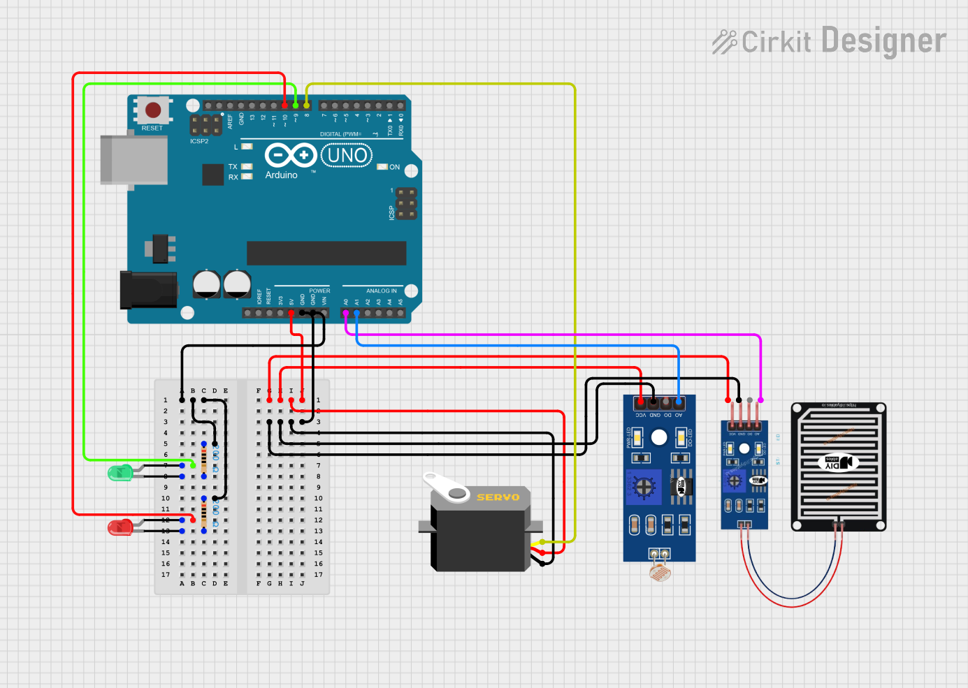
Circuit Documentation
Summary
This circuit is designed to monitor rain and light levels using sensors and control a servo motor and LEDs based on the sensor readings. The circuit uses an Arduino UNO microcontroller to read data from a rain sensor and a light-dependent resistor (LDR). Based on the sensor inputs, the Arduino controls a servo motor to open or close a cover and lights up either a red or green LED to indicate the status.
Component List
Arduino UNO
- Description: A microcontroller board based on the ATmega328P.
- Pins: UNUSED, IOREF, Reset, 3.3V, 5V, GND, Vin, A0, A1, A2, A3, A4, A5, SCL, SDA, AREF, D13, D12, D11, D10, D9, D8, D7, D6, D5, D4, D3, D2, D1, D0
Servo
- Description: A servo motor used for precise control of angular position.
- Pins: gnd, vcc, pulse
LDR (Light Dependent Resistor)
- Description: A sensor that changes its resistance based on the light intensity.
- Pins: A0, D0, GND, VCC
Rain Sensor
- Description: A sensor that detects the presence of rain.
- Pins: AO, DO, GRD, VCC
Resistor (200 Ohms)
- Description: A resistor with a resistance of 200 Ohms.
- Pins: pin1, pin2
LED: Two Pin (red)
- Description: A red LED.
- Pins: cathode, anode
Resistor (200 Ohms)
- Description: A resistor with a resistance of 200 Ohms.
- Pins: pin1, pin2
LED: Two Pin (green)
- Description: A green LED.
- Pins: cathode, anode
Wiring Details
Arduino UNO
5V connected to:
- Rain Sensor (VCC)
- Servo (vcc)
- LDR (VCC)
GND connected to:
- Rain Sensor (GRD)
- Servo (gnd)
- LDR (GND)
- Resistor (pin1) of both resistors
D9 connected to:
- Green LED (anode)
D10 connected to:
- Red LED (anode)
A0 connected to:
- Rain Sensor (AO)
A1 connected to:
- LDR (A0)
D8 connected to:
- Servo (pulse)
Servo
gnd connected to:
- Arduino UNO (GND)
vcc connected to:
- Arduino UNO (5V)
pulse connected to:
- Arduino UNO (D8)
LDR
GND connected to:
- Arduino UNO (GND)
VCC connected to:
- Arduino UNO (5V)
A0 connected to:
- Arduino UNO (A1)
Rain Sensor
GRD connected to:
- Arduino UNO (GND)
VCC connected to:
- Arduino UNO (5V)
AO connected to:
- Arduino UNO (A0)
Resistor (200 Ohms)
pin1 connected to:
- Arduino UNO (GND)
pin2 connected to:
- Green LED (cathode)
Resistor (200 Ohms)
pin1 connected to:
- Arduino UNO (GND)
pin2 connected to:
- Red LED (cathode)
LED: Two Pin (red)
cathode connected to:
- Resistor (pin2)
anode connected to:
- Arduino UNO (D10)
LED: Two Pin (green)
cathode connected to:
- Resistor (pin2)
anode connected to:
- Arduino UNO (D9)
Code Documentation
#include <Servo.h>

const int rainSensorPin = A0;
const int lightsensorPin = A1;
const int servoPin = 8;
const int merahPin = 10;
const int hijauPin = 9;

Servo myServo;

void setup() {
  // Set up the rain sensor pin as an input
  pinMode(rainSensorPin, INPUT);
  pinMode(lightsensorPin, INPUT);
  pinMode(merahPin, OUTPUT);
  pinMode(hijauPin, OUTPUT);
  // Set up the servo motor
  myServo.attach(servoPin);
  myServo.write(0);

  Serial.begin(9600);
}

void loop() {
  // Read the state of the rain sensor
  int rainState = digitalRead(rainSensorPin);
  int lightState = digitalRead(lightsensorPin);
  // If the rain sensor detects rain (LOW), rotate the servo motor continuously

  Serial.print("Rain sensor: ");
  Serial.println(rainState);
  Serial.print(" | Light sensor: ");
  Serial.println(lightState);

  if (rainState == LOW || lightState == HIGH)  {
    digitalWrite(merahPin, HIGH);
    digitalWrite(hijauPin, LOW);
    myServo.write(180);
    Serial.println("Jemuran Ditutup!"); // Rotate the servo motor to 90 degrees
  }
  else {
    // If no rain is detected, stop the servo motor
    digitalWrite(merahPin, LOW);
    digitalWrite(hijauPin, HIGH);
    myServo.write(0);
    Serial.println("Jemuran Dibuka!"); // Rotate the servo motor to 0 degrees
  }
  delay(500);
}
This code sets up the Arduino to read from the rain sensor and the LDR, and control the servo motor and LEDs based on the sensor readings. The servo motor is used to open or close a cover, and the LEDs indicate the status (red for closed, green for open). The code also prints the sensor states to the serial monitor for debugging purposes.