Cirkit Designer
Your all-in-one circuit design IDE
Home /
Project Documentation
Raspberry Pi Zero and Adafruit TCS34725 RGB Color Sensor for Color Detection
Circuit Documentation
Summary
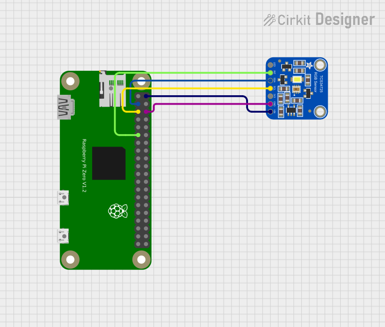
This document provides a detailed overview of a circuit that integrates a Raspberry Pi Zero with an Adafruit TCS34725 RGB Color Sensor. The Raspberry Pi Zero serves as the main controller, interfacing with the color sensor to read RGB values. The connections between the components are established through various GPIO pins, power, and ground connections.
Component List
Raspberry Pi Zero
- Description: A small, affordable, and versatile single-board computer.
- Pins:
- 5V
- 3.3V
- GPIO2 (SDA)
- GND
- GPIO3 (SCL)
- GPIO14
- GPIO4
- GPIO15
- GPIO18
- GPIO17
- GPIO27
- GPIO23
- GPIO22
- GPIO24
- GPIO10
- GPIO25
- GPIO9
- GPIO8
- GPIO11
- GPIO7
- ID_SC
- ID_SD
- GPIO5
- GPIO12
- GPIO6
- GPIO13
- GPIO16
- GPIO19
- GPIO20
- GPIO26
- GPIO21
- hdmi rpi
- usb rpi
- usb rpi2
- sd rpi
Adafruit TCS34725 RGB Color Sensor
- Description: A color sensor that can detect and measure RGB values.
- Pins:
- LED_EN
- INT
- SDA
- SCL
- +3V3
- GND
- VIN
Wiring Details
Raspberry Pi Zero
- GPIO17 is connected to INT of the Adafruit TCS34725 RGB Color Sensor.
- GPIO2 (SDA) is connected to SDA of the Adafruit TCS34725 RGB Color Sensor.
- GPIO3 (SCL) is connected to SCL of the Adafruit TCS34725 RGB Color Sensor.
- GND is connected to GND of the Adafruit TCS34725 RGB Color Sensor.
- 5V is connected to VIN of the Adafruit TCS34725 RGB Color Sensor.
Adafruit TCS34725 RGB Color Sensor
- INT is connected to GPIO17 of the Raspberry Pi Zero.
- SDA is connected to GPIO2 (SDA) of the Raspberry Pi Zero.
- SCL is connected to GPIO3 (SCL) of the Raspberry Pi Zero.
- GND is connected to GND of the Raspberry Pi Zero.
- VIN is connected to 5V of the Raspberry Pi Zero.
Code Documentation
No microcontroller code is provided for this circuit.
This document provides a comprehensive overview of the components and their interconnections in the circuit. For further details or modifications, please refer to the respective datasheets and manuals of the components used.